Part 03: Motor A
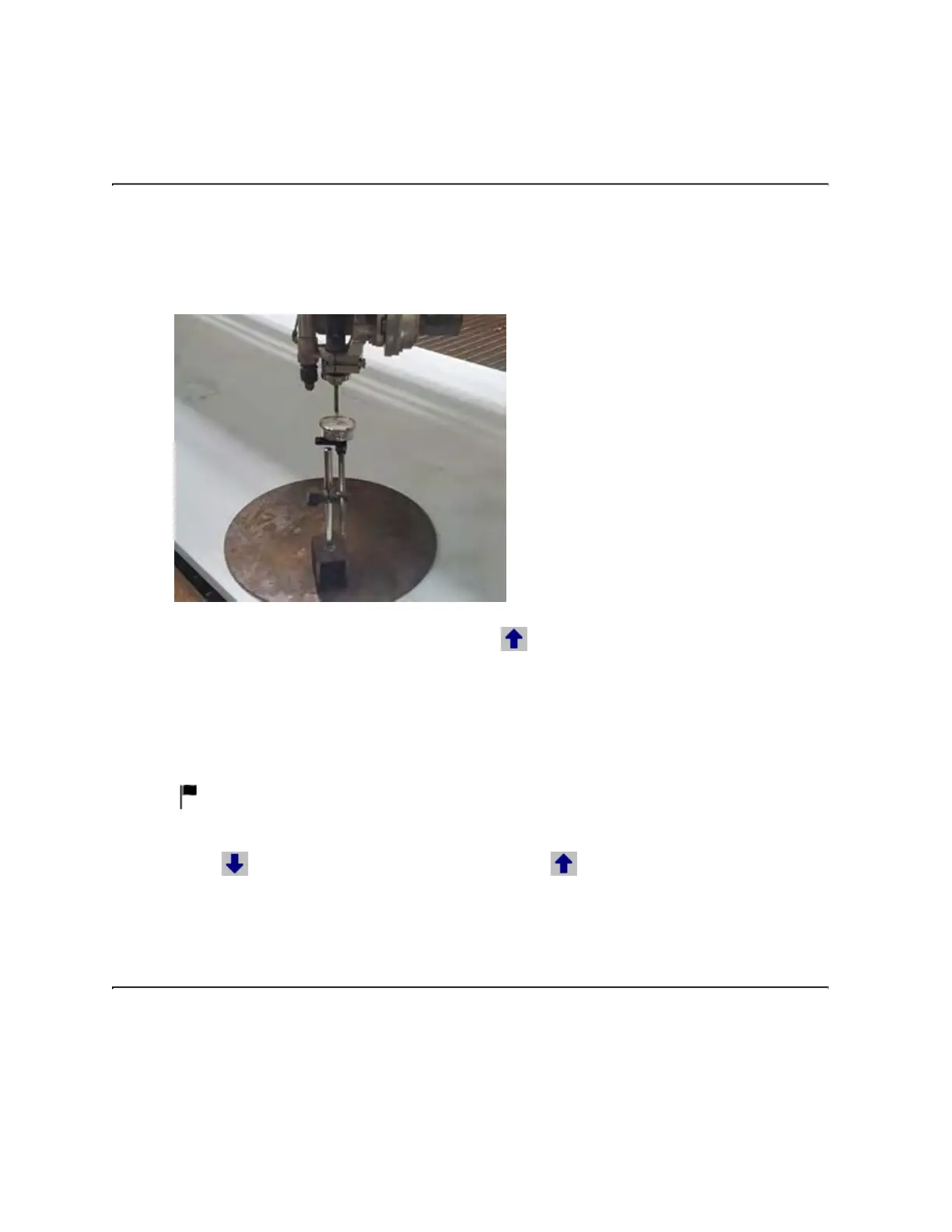
1. Place the ferrous plate into position just under the motors, and then place the base onto the
plate and engage the magnet.
2. Position the indicator tip—parallel to the A-axis motor—on the mixing tube. Make sure it's
directly below the nozzle nut, and then zero the dial gauge.
3. In the Straightness Adjustment dialog, select .
4. Record the measurement, paying particular attention to whether the value is positive (+) or
negative (–).
◦ If it went clockwise, it is a positive value. If it went counterclockwise, it is a negative value.
5. Under Motor A, enter the value in the Bottom reading box, and then select Apply—the dial
indicator should go to zero or just past it.
Remember to enter the minus sign (–) if it's a negative value. You don't have to enter a
positive sign (+) for a positive value.
6. Select
. Zero the dial gauge again, and then select . If the indicator moved more than
0.001 inches, repeat steps 3–6 until successful.
Part 04: Last steps
1. Remove the indicator and magnetic base from the table.
2. In the Straightness Adjustment dialog, select OK. You will get a message to remove
anything in the vicinity of the wrist because the ABZ will be returning to machine home.
3. Install the mixing tube spacer and spray shield, and then cut a test part to verify the cut edge is
straight from top-to-bottom.
© 2021 Flow International Corp.
Retrieved from Flow KB on April 19, 2021 PST
Calibrations and alignments