5700A/5720A Series II
Operators Manual
4-14
Caution
Use only cables with correct voltage ratings.
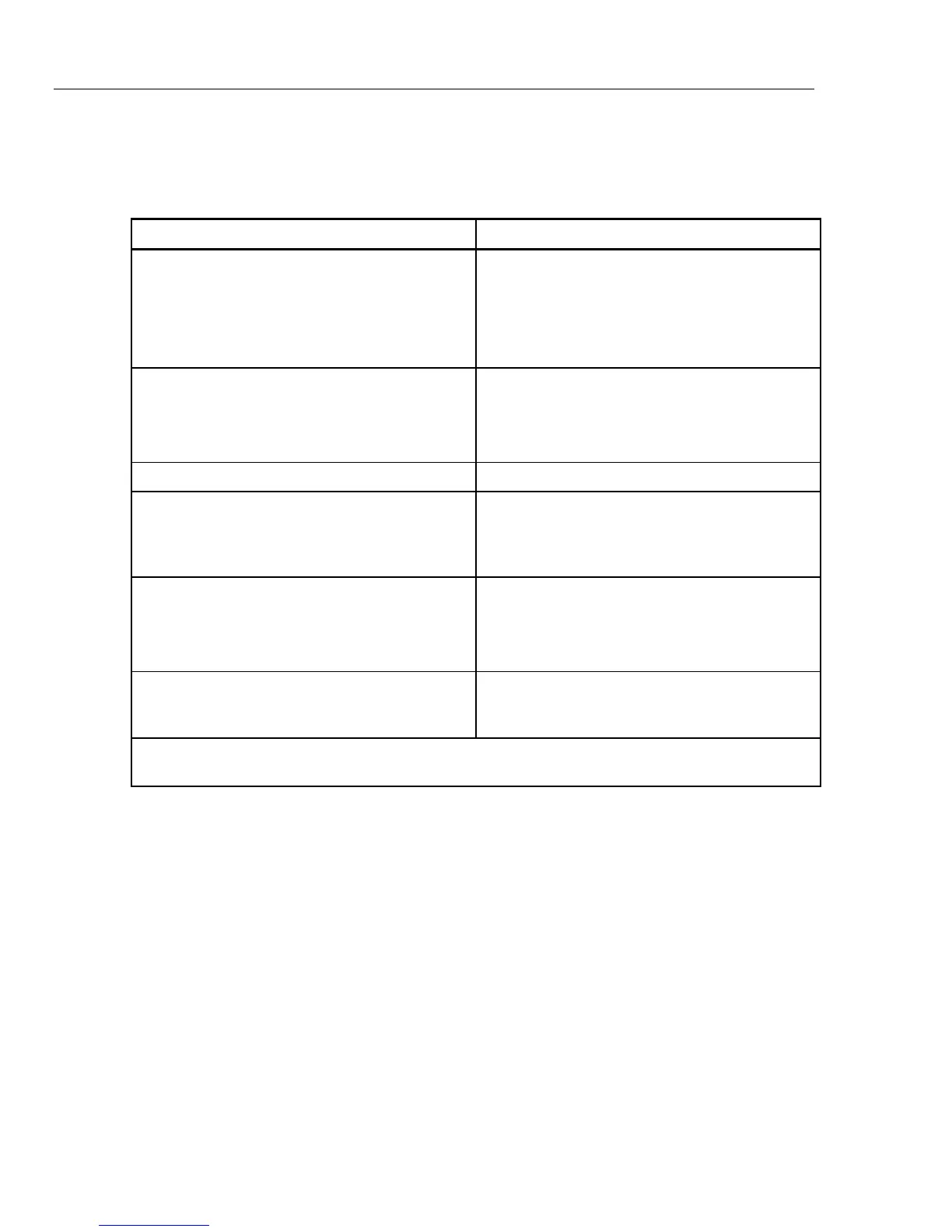
Table 4-1. Auxiliary Amplifier Data
Output Function Cable Recommendations
DC voltage
AC voltage ≤10 kHz
AC current ≤2A, ≤10 kHz
DC current ≤2A
Resistance
Low Thermal EMF Test Leads [Note 1]
5440A-7002 (banana plugs) or
5440A-7003 (spade lugs) 2 ft. (61 cm.) cable
(If external sensing is required, use a twisted
shielded pair.)
AC voltage >10 kHz SENSE/GUARD: Triaxial cable or Twinax (e.g.,
Alpha 2829/2), OUTPUT: Coaxial
Or: SENSE: Coaxial, OUTPUT: Coaxial
GUARD Lead: Separate wire
AC current with guard Triaxial cable
Wideband AC 6-foot (2 m) 50Ω coaxial cable with type “N” male
connector supplied with the option. A 50Ω
feedthrough terminator is also supplied for
connecting to meters with an impedance >50Ω.
Voltage-boosted output, 5725A Low Thermal EMF Test Leads [Note 1]
5440A-7002 (banana plugs) or
5440A-7003 (spade lugs)
(Output is at the calibrator’s front panel.)
Current-boosted output, 5725A 16-gauge or heavier twisted pair insulated wire, as
short as possible to minimize resistance and
inductance. (Output is at the amplifier terminals.)
1. Spade lugs provide a slightly better thermal EMF performance. However, some UUTs have repressed
banana connectors that cannot accommodate spade lugs.
4-19. When to Use External Sensing
External sensing is normally required only when you are calibrating a device that draws
enough current to produce a significant voltage drop in the cables. An example of such a
case is using the calibrator as an external dc voltage reference for an AC/DC transfer
standard. In this example, the calibrator is sourcing 1V dc into a Fluke 540B AC/DC
Transfer Standard. The 180Ω input impedance results in a current flow of approximately
5 mA. The calibrator’s 90-day uncertainty at 1V is specified to be ±(6 ppm + 1.2 uV) or ±
7.2 µV. Cumulative lead and contact resistances of as little as 2 mΩ would cause a
voltage drop greater than the total uncertainty of the calibrator. External sensing
eliminates this error.
The normal power-up state of the calibrator is external sensing off, with an internal
connection between the SENSE and OUTPUT automatically made. This is the state
achieved by pressing X so that the indicator is off.