5700A/5720A Series II
Operators Manual
4-50
4-51. Setting Output Limits
An output limit feature is available to help prevent accidental damage to a UUT from
overcurrent or overvoltage conditions. This feature allows you to preset the maximum
positive and negative allowable voltage or current output. Entry limits you set prevent
any input greater than the limit from being activated by entry through the front panel
keys or the output adjustment controls. Positive limits for voltage and current set the
limits for ac voltage and current. Default entry limits after power-up or
r are the
specified maximum and minimum for each output function.
4-52. Setting Voltage and Current Limits
To set voltage and current entry limits, proceed as follows from r, the power-up state,
or any direct operation menu:
1.
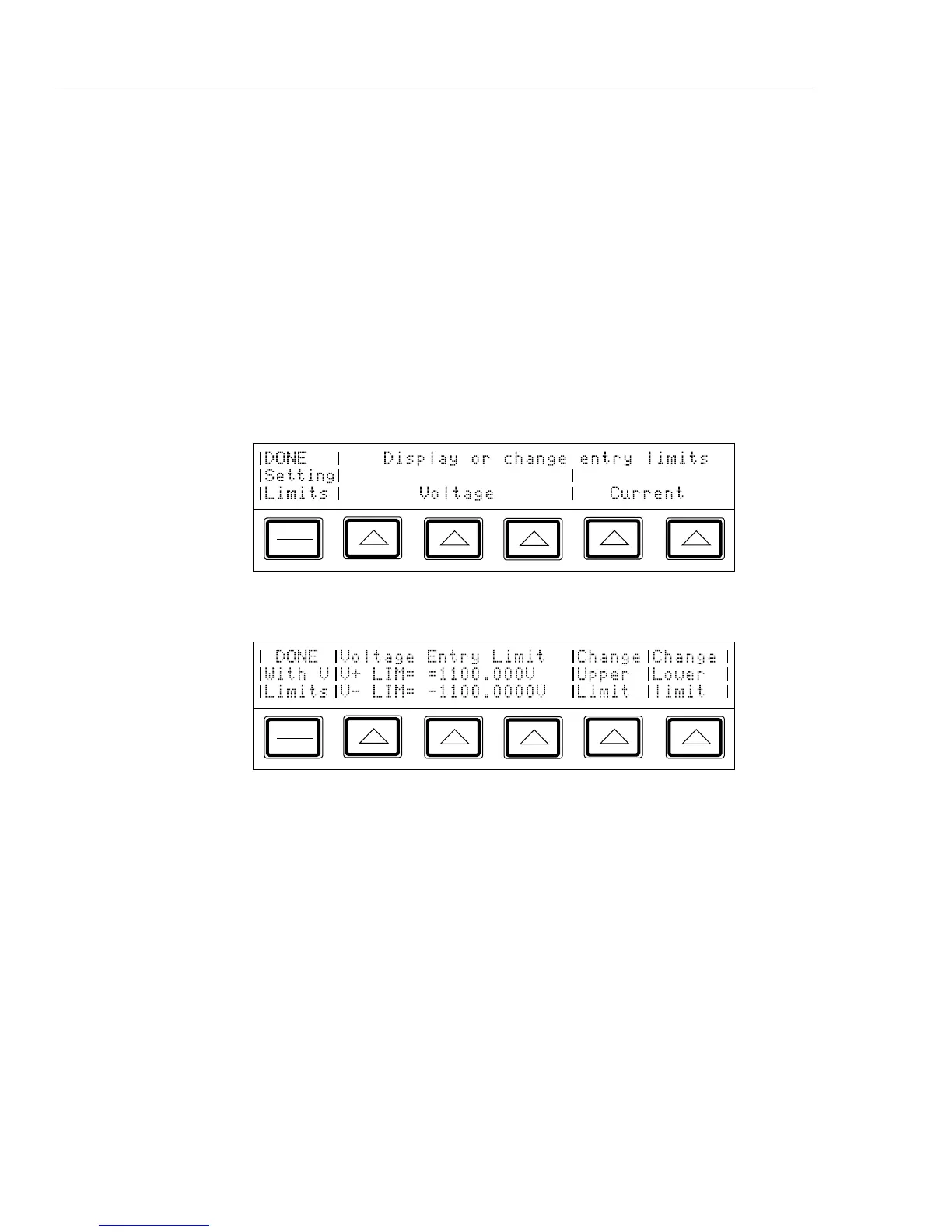
Press L. The display changes to:
PREV
MENU
2.
Press one of the softkeys under “Voltage.” The display changes to:
PREV
MENU
3.
Press the “Change Upper Limit” or the “Change Lower Limit” softkey, then press the
numeric keys for the desired voltage limit and
U, m, or K if necessary,
followed by
E.
Note
The upper voltage limit sets the limits for both dc and ac voltage.
4. Press P.