5700A/5720A Series II
Operators Manual
4-38
8. When the “Range” softkey is set to “AUTO”, the amplifier automatically turns off
whenever a current level within the range of the calibrator is set. Setting the “Range”
softkey to “LOCKED” disables this auto shut-off, so you can use the amplifier at
lower current levels.
Note
You can have the 5725A source a current below 2.2A to take advantage of
the amplifier's higher compliance voltage. To do so, press the “Range”
softkey to lock onto the 11A range when the calibrator is set for over 2.2A,
or set the lower current and press B O to turn on the amplifier.
9. To deactivate the amplifier, press B again.
4-35. Checking the Calibrator’s Uncertainty Specification
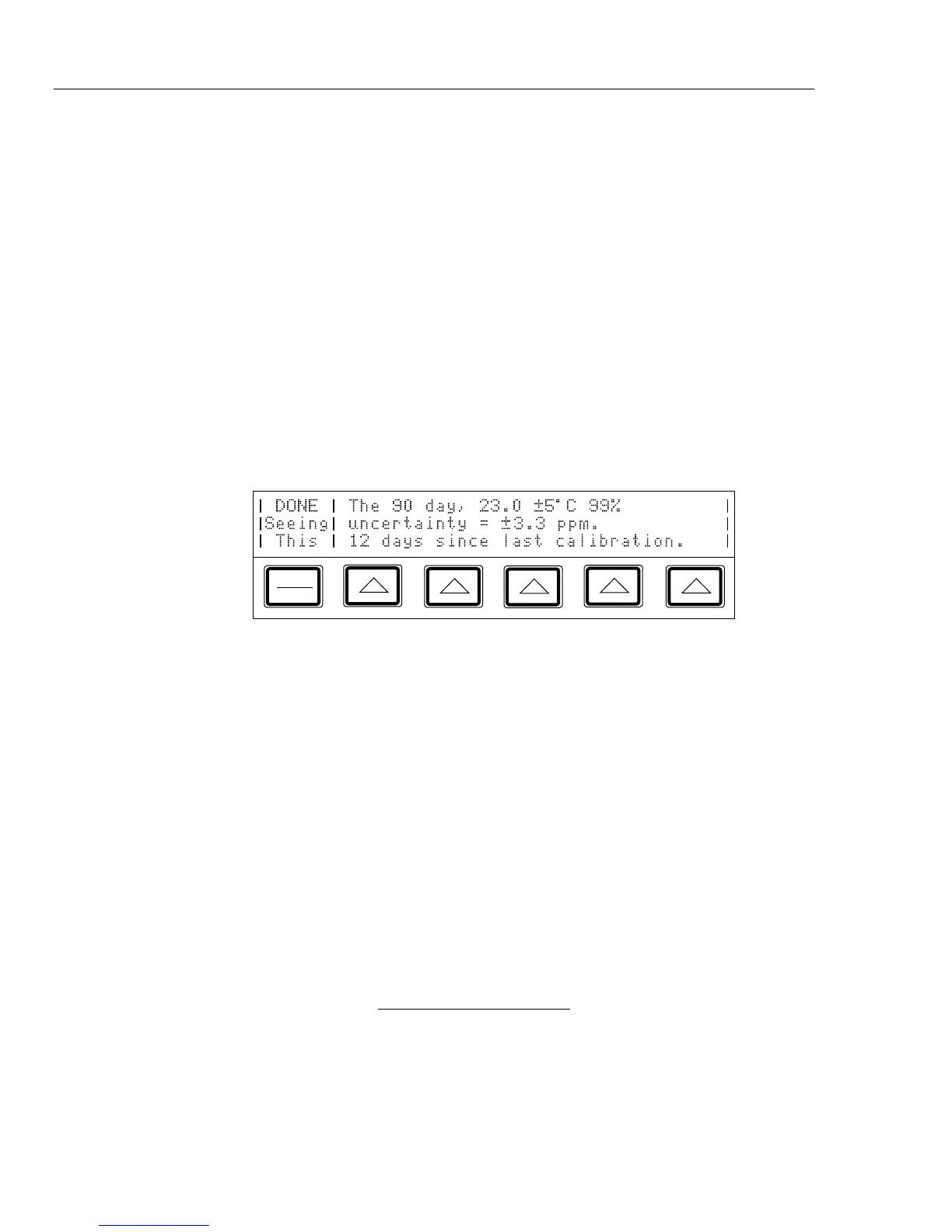
At any time during front panel operation, you can display the uncertainty specification of
the present output of the calibrator by pressing s, which opens a display similar to the
one shown below. To return to normal operation, press P.
PREV
MENU
4-36. Error Mode Operation
The output adjustment controls (arrow keys and the rotary knob) are used to adjust the
output of the calibrator incrementally (except in the resistance function). While this
happens, the Control Display computes and displays the difference between the adjusted
output and the reference level in ±% or ±ppm (parts per million). The reference level is
the original output setting before you adjusted it. When this capability is used to adjust
the output until the UUT reads correctly, the displayed difference is the UUT error for
that output setting. The error is displayed in ±% unless it is ±20 ppm or less.
For example, suppose you set the calibrator to output 10.00000V, and the UUT reading is
high. To determine the error, use the output adjustment controls to adjust the calibrator
until the UUT reads 10.0000V. If, for example, the calibrator’s output display now reads
9.993900, the calibrator calculates and displays a UUT error of +0.0610% on the control
display.
The calibrator uses this formula to calculate the UUT error:
Error =
(Reference) - (Final Output)
(Reference)
x 100%
The rotary knob is also a convenient way to change the frequency during ac voltage
testing. To adjust frequency in error mode, for example when testing a meter's flatness,
press
a. The 10 Hz digit of the frequency line is highlighted. Press < twice. Now
when you turn the knob, the output frequency increases or decreases 1 kHz per knob
click.