Remote Operation
Local-to-Remote State Transitions 5
5-43
5-22. Local-to-Remote State Transitions
The calibrator can be operated either locally from the front panel, or remotely, by
responding to remote control commands. In addition to front panel and remote control
operation, the controller can be placed in a local lockout condition at any time by remote
command. When combined, the local, remote, and lockout conditions yield four possible
operating states:
• Local (Front Panel Operation)
The calibrator responds to local and remote commands, but only remote commands
that do not affect the state of the calibrator are allowed to execute. (For example
OUT?, which returns the value of the calibrator’s output setting is executable in the
local state, but OUT, which sets the output to another value cannot be executed in
local state.)
• Local with Lockout
Local with lockout is identical to local, except the calibrator will go into the remote
with lockout state instead of the remote state when it receives a remote command.
The local with lockout state is entered by executing the LOCKOUT statement from
an IEEE-488 controller, or by sending the LOCKOUT command froma serial
controller.
• Remote
When the Remote Enable (REN) line is asserted and the controller addresses the
calibrator as a listener, it enters the remote state. These conditions are met, for
example, when a 1722A executes the BASIC statement “REMOTE \ PRINT @4
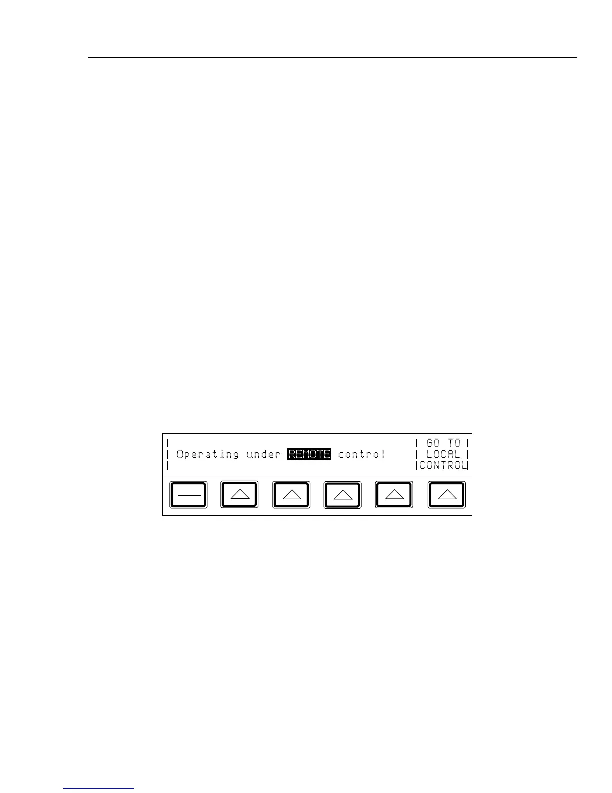
‘OUT 10MV’” if the calibrator's address is 4. In the remote state, Control Display
changes to:
PREV
MENU
Front panel operation is restricted to use of the power switch and the “Go To Local
Control” softkey. Pressing this softkey or sending the GTL (Go To Local) interface
message returns the calibrator to the local state. (One way to send the GTL interface
message in some controllers is by executing the LOCAL statement.)