Remote Operation
Checking the Calibrator’s Status 5
5-45
5-23. Checking the Calibrator’s Status
The controller has access to six status registers for the calibrator, which indicate the
calibrator’s conditions in the as shown in Figure 5-1. Each register bit is explained under
separate headings for each register. Table 5-6 lists each register and its remote
commands.
In addition to the status registers, the Service Request control line, SRQ (available only
when using an IEEE-488 controller) and a 16-element buffer called the Fault Queue
provide status information.
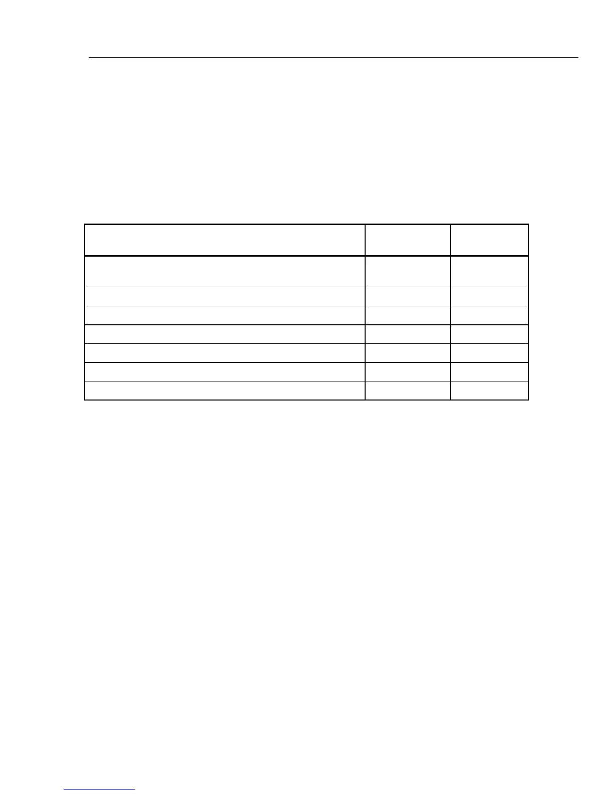
Table 5-6. Status Register Summary
Register READ
Command
WRITE
Command
Enable
Register
Serial Poll Status Byte (STB) *STB?
(or SPL( ) for some controllers)
None SRE
Service Request Enable Register (SRE) *SRE? *SRE None
Event Status Register (ESR) *ESR? None ESE
Event Status Enable Register (ESE) *ESE? *ESE None
Instrument Status Register (ISR) ISR? None None
Instrument Status Change Register (ISCR) ISCR? None ISCE
Instrument Status Change Enable Register (ISCE) ISCE? ISCE None