Installation
Accessing the Fuse 2
2-5
2-7. Accessing the Fuse
Caution
To prevent instrument damage, verify that the correct fuse is
installed for the line voltage setting.
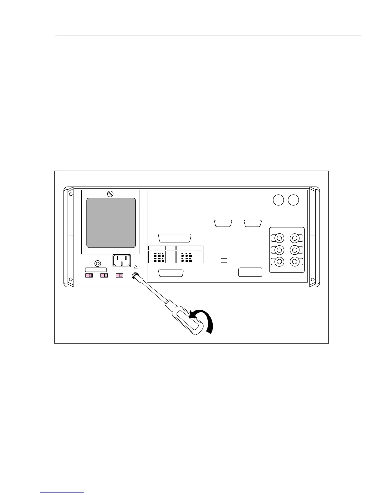
The line power fuse is accessible on the rear panel. The fuse rating label to the right of
the fuse holder (labeled F1) shows the correct replacement fuse rating for each line
voltage setting. To check or replace the fuse, refer to Figure 2-1 and proceed as follows:
1. Disconnect line power.
2. Using a standard screwdriver, loosen the fuse holder by turning the slot labeled F1
until the cap and fuse pop free.
3. Replace the fuse and holder.
VOLTAGE
SELECTION
FUSE-F1
T 3A
250V
(SB)
100V
S2 S3 S4
110V
115V
120V
VOLTAGE
SELECTION
FUSE-F1
T 1.5A
250V
(SB)
200V
S2 S3 S4
220V
230V
240V
CHASSIS
GROUND
S2 S3 S4
FUSE -F1
!
Figure 2-1. Accessing the Fuse