Front Panel Operation
Linearity Checking Using Offset and Scale 4
4-47
4-50. Linearity Checking Using Offset and Scale
Using the calibrator’s offset and scaling features, you can remove a UUT's offset and
scale errors to isolate and display linearity error. The following procedure is an example
that uses
o and S to determine both scale and linearity error of a 4 1/2-digit DMM.
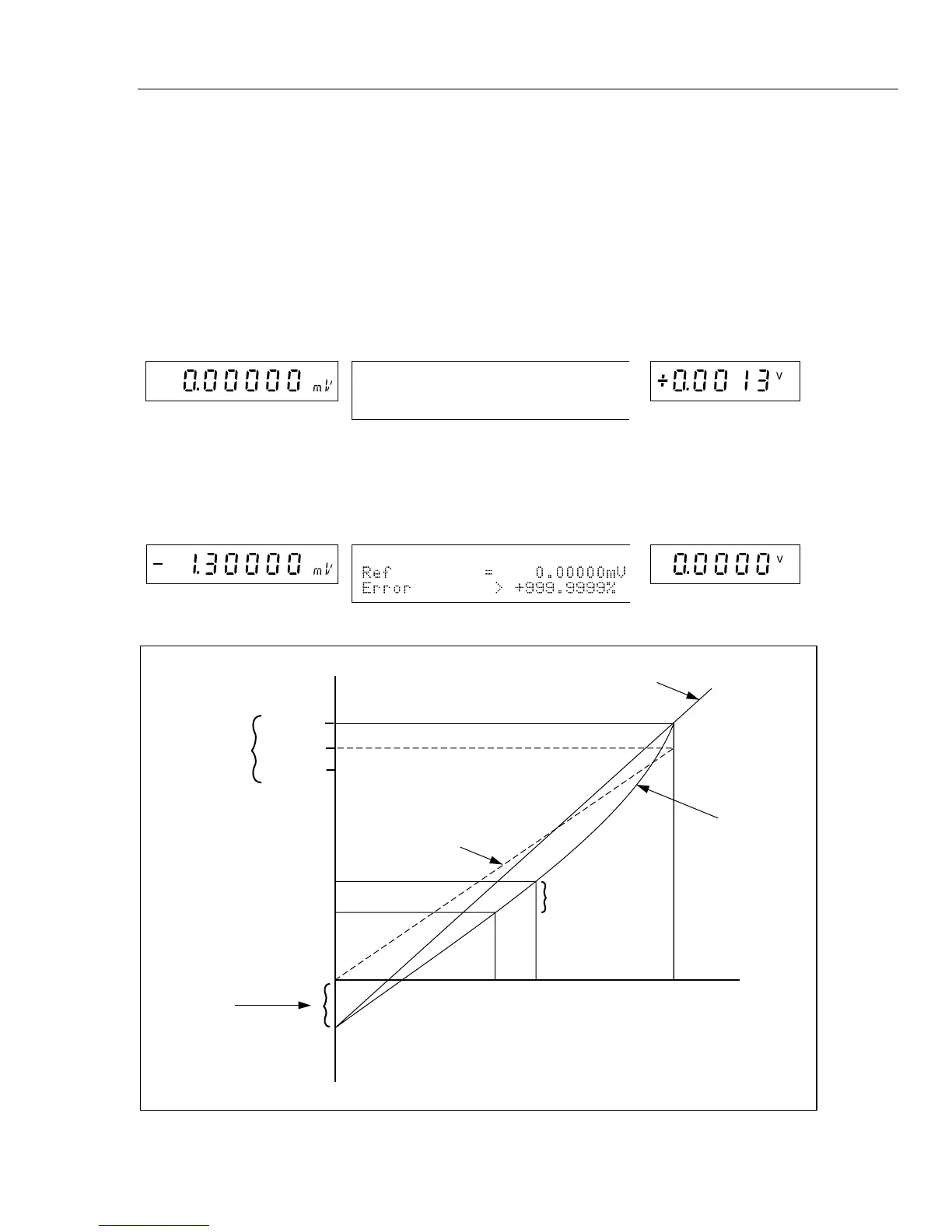
In this example, the DMM is set to the 20V dc range, and the calibrator is connected to
the DMM. Figure 4-10 illustrates all three types of errors that are detected by the
calibrator. The numbers in the graph correspond to the conditions encountered in the
example.
1.
Set the calibrator to 0 mV in standby. The displays change to:
Output Display
Control Display
UUT (DMM) Display
2.
Use the output adjustment controls (the rotary knob and arrow keys) to adjust the
calibrator’s output for a reading of 0V on the DMM. The displays change to:
Output Display
Control Display
UUT (DMM) Display
CALIBRATOR
VOLTAGE
0
-1.3 mV
METER READING
OFFSET
ERROR =
+1.3 mV
10.000
10.007
19.900
19.9017
19.8987
10.000208
9.993208
LINEAR
RESPONSE
ACTUAL
METER
RESPONSE
LINEARITY
ERROR
SCALE
ERROR
19.9
IDEAL
RESPONSE
Figure 4-10. Meter Response vs. Stimulus