5700A/5720A Series II
Operators Manual
4-36
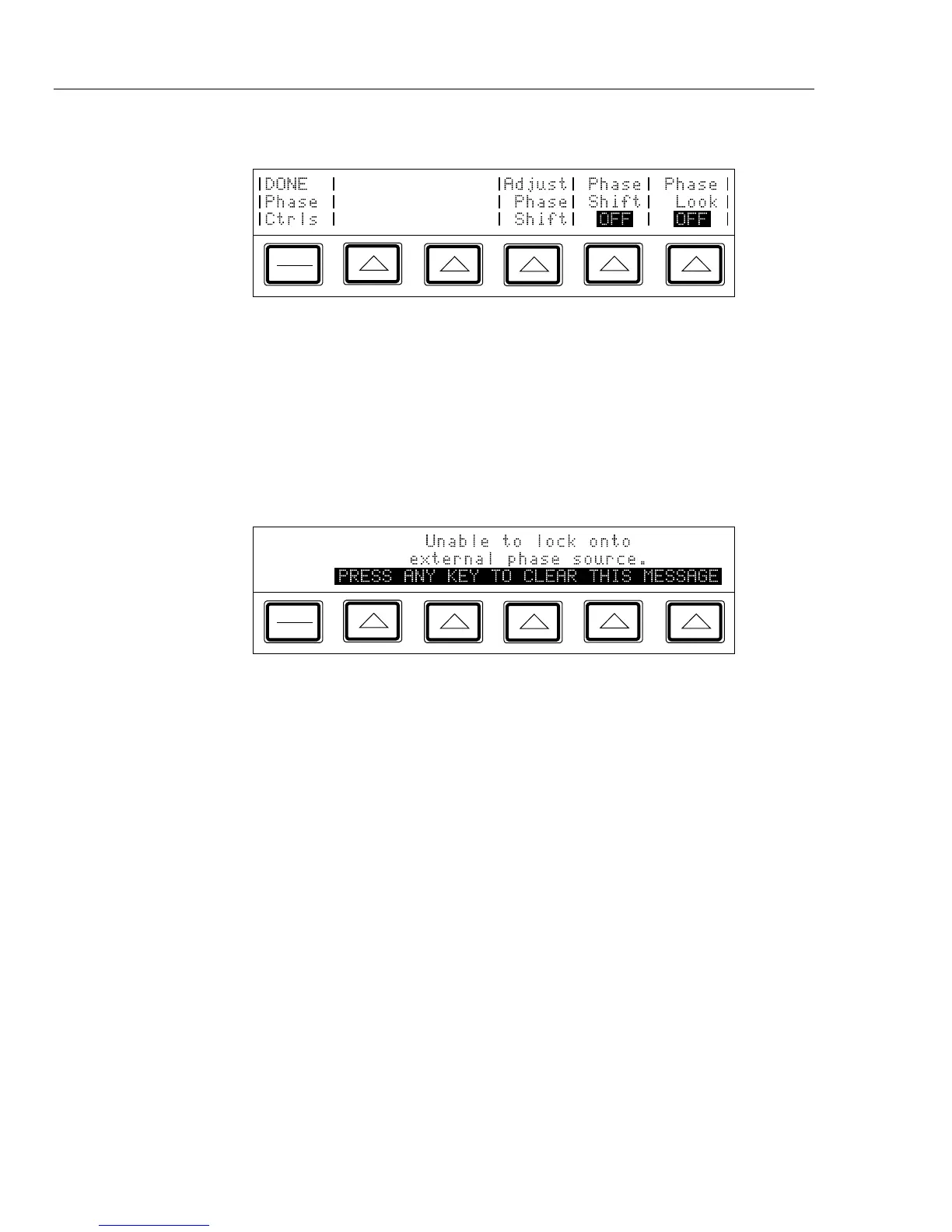
3. Press the “Phase Ctrls Menu” softkey. The Control Display appears as shown below:
PREV
MENU
4. Turn on the external signal source.
5. Set the calibrator’s frequency to within 2% of the external source frequency.
6. Press the “Phase Lock” softkey. This locks the calibrator's main output signal in
phase with the external signal applied to the rear panel PHASE LOCK IN BNC
connector. When phase locking is successful, the (∅-LOCK annunciator on the
Output Display lights.
7. Observe the Control Display. If the calibrator cannot lock onto the external signal for
any reason, it displays the following message:
PREV
MENU
8. To reactivate the numeric keypad for controlling the output, press P. Phase locking
remains active until you change the frequency or turn off phase lock using the
“Phase Lock” softkey.
4-33. Using an Auxiliary Amplifier
You can increase the output capability of the calibrator by using an auxiliary amplifier.
The calibrator has rear panel connectors that interface with four different amplifiers.
Three amplifiers can be connected to the calibrator simultaneously, but only one
amplifier can be designated as the voltage boost and one amplifier as the current boost in
the setup menu. (And only one output can be active at a time.) Table 1-1 shows the
ranges and functions supported by the 5725A. The choice of active amplifier and be
changed dynamically in a remote system, since such systems can control any front panel
function.
During boost operation, you operate the amplifier from the calibrator’s front panel. The
calibrator computes and supplies the correct excitation voltages to drive the amplifier.
The Output Display on the calibrator always shows the actual output of the amplifier, not
the excitation output of the calibrator. In general, the amplifier is activated automatically
by selecting an output amplitude only available in its range. In some cases, B is used to
activate and deactivate the selected amplifier. Refer to the following text for specific
operation instructions for each type of amplifier.