5700A/5720A Series II
Operators Manual
4-40
4-40. Using Error Mode
When you enter error mode from any output function except resistance, the least
significant digit on the Output Display is highlighted. Entering error mode by pressing
a selects the frequency line for adjustment first (but only if the frequency is not zero).
When you turn the rotary knob, the highlighted digit increments or decrements. Turning
the knob clockwise makes the number more positive; turning the knob counterclockwise
makes the number more negative. As you increment a digit past 9 or decrement a digit
past 0, the adjacent digit carries.
< and > select digits to the right and left, and a
selects the upper line (amplitude) and lower line (frequency).
If you attempt to adjust the output beyond the capability of the calibrator, the calibrator
beeps and does not allow the change.
You can quickly verify accuracy of different ranges of a UUT by pressing
Y and Z.
When you are in error mode and you press these keys, the calibrator’s output and the new
reference are set to 10 times or one tenth the previous reference value.
In the resistance output function, the edit controls produce a display of the UUT error in a
similar way, except the output of the calibrator does not change as you turn the knob.
Instead, a reading on the Control Display changes, allowing you to match it to the reading
on the UUT. As you change the reading, the calibrator computes and displays UUT error.
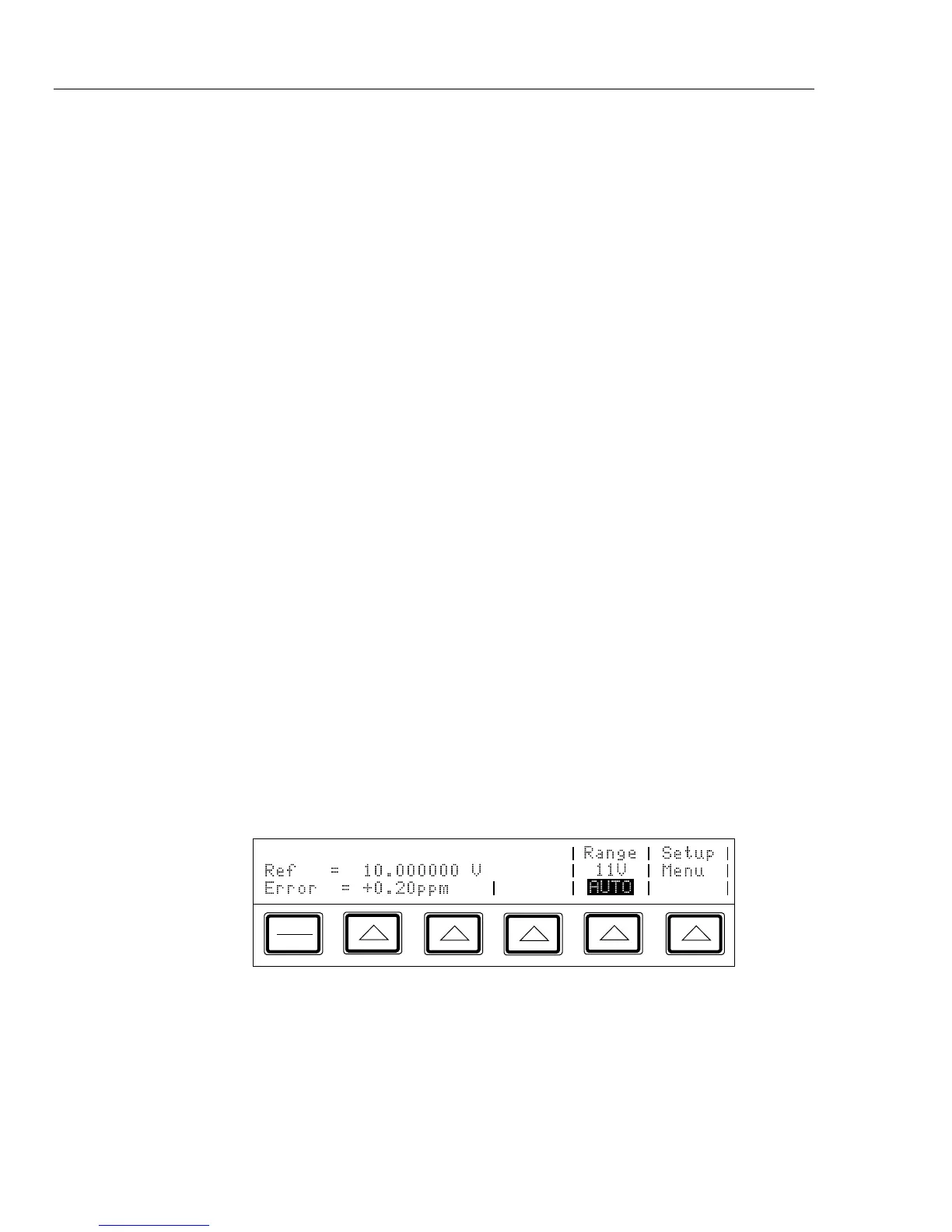
4-41. Reading the UUT Error: AC and DC Voltage and Current Output
Proceed as follows to read the error of the UUT in the ac and dc voltage and current
output functions:
1.
Set the desired calibration voltage or current, as previously described under “Setting
the Output.”
2.
Use the output adjustment controls as required to achieve a reading on the UUT equal
to the original entry on the calibrator. To
increment or decrement a higher-order digit,
press
<. As you approach the reference value, work progressively back towards
the
LSD (least-significant digit) on the calibrator’s output display as necessary by
pressing
>. You only need to go one digit past the LSD of the UUT; digits below
that are beyond the resolution
of the UUT. The UUT error appears on the Control
Display as
shown: (This example assumes that the calibrator is in the dc voltage
function.)
PREV
MENU