Front Panel Operation
Setting the Output 4
4-27
4-27. DC Current Output
To set a dc current output, proceed as follows:
1. Make sure the calibrator is in standby (STANDBY annunciator lit). Press O if
necessary.
2. If the UUT is not connected, connect it now as described earlier in this chapter under
“Connecting the Calibrator to a UUT.”
3. Set the UUT to measure dc current on the appropriate range.
4. Press up to seven numeric keys to select an amperage level.
5. To change the polarity of your entry, press +.
6. Press U or m if necessary.
7. Press A.
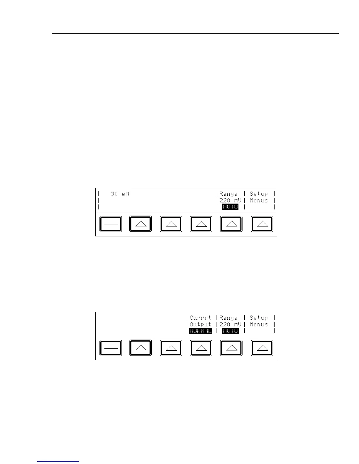
8. The Control Display now shows the amplitude of your entry. If you made an entry
error, press C to clear the display, then reenter the value. The following illustration
of the Control Display assumes an entry of 30 mA:
PREV
MENU
9. Press E. The calibrator clears your entry from the Control Display and copies
it into the Output Display. No current is available at the output terminals, however,
until you press O.
10. Press O to activate the calibrator’s output. The UUT will now respond to the
applied current.
Three softkey labels appear on the Control Display in the dc current function: “Currnt
Output”, “Range”, and “Setup Menus”:
PREV
MENU