5700A/5720A Series II
Operators Manual
4-26
9. Press up to five numeric keys to select a frequency, followed by K or m if
necessary. The Control Display now shows the amplitude and frequency of your
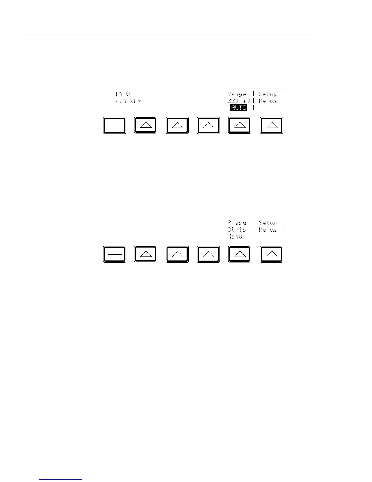
entry. If you made an entry error, press C to clear the display, then reenter the
value. The following illustration of the Control Display assumes an entry of 2.8 kHz:
PREV
MENU
10. Press E. The calibrator clears your entry from the Control Display and copies
it into the Output Display. No voltage is available at the output terminals, however,
until you press O.
11. Press O to activate the calibrator’s output. The UUT will now respond to the
applied voltage.
Two softkey labels appear on the Control Display in the ac voltage function: “Phase Ctrls
Menu” and “Setup Menus”:
PREV
MENU
• The “Phase Ctrls Menu” softkey activates the front panel controls for phase output.
(Instructions for setting a phase output are under “Phase Output,” later in this
chapter.)
• The “Setup Menus” softkey opens the setup menu.
Note
The calibrator stays in the ac function after you enter a non-zero frequency.
If you want to change back to dc, simply enter a frequency of 0 Hz or a
signed voltage.