5700A/5720A Series II
Operators Manual
6-4
Table 6-1. RS-232C Interface Parameter Choices
Parameter Choices Default Setting
Data Bits 7 or 8 8
Stop Bits 1 or 2 1
Flow Control Ctrl S/Ctrl Q, (XON/XOFF), RTS, or none Ctrl S/ Ctrl Q
Parity Checking Odd, even, or none None
Baud Rate 110, 300, 600, 1200, 2400, 4800, 9600, or 19200 9600
Timeout Period 0 to 30 seconds 0 (no timeout)
EOL (End of Line) CR, LF, or CR LF CR LF
EOF (End of File Any two ASCII characters No characters
6-3. Setting Up and Connecting the Serial Interface
Refer to the specifications for your peripheral device, and proceed as follows to set up the
serial interface for your application:
1. Turn off the power. Connect an RS-232C null-modem cable such as Fluke accessory
Y1702 or Y1703 to the rear panel RS-232C connector and to the peripheral device.
2. Power up the calibrator.
3. Press the following sequence of softkeys:
“Setup Menus” → “Instmt Setup” → “Remote Port Setup” → “RS-232 Port Setup”
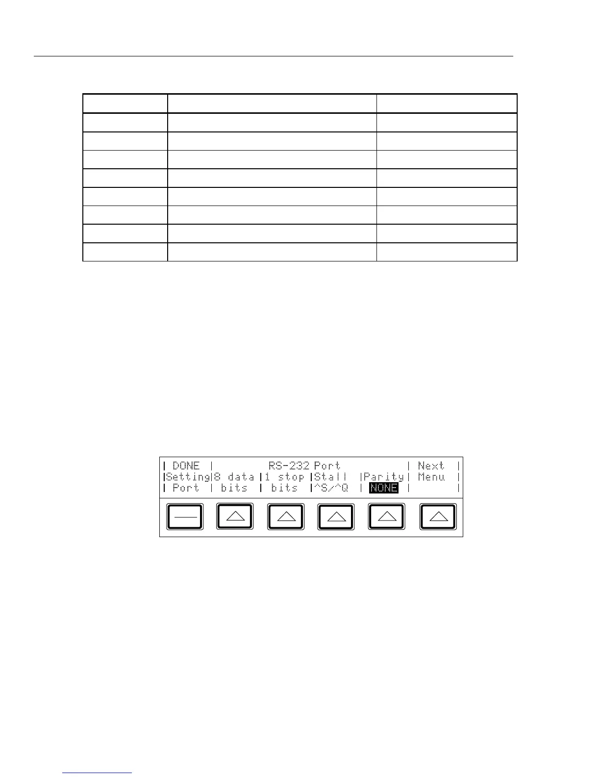
The display changes to:
PREV
MENU
4. Set the number of data bits with the “data bits” softkey.
5. Set the number of stop bits with the “stop bits” softkey.
6. Select a method of stall control with the “Stall” softkey.
7. Select the parity mode with the “Parity” softkey.