5700A/5720A Series II
Operators Manual
4-22
HI
HI
LO
LO
HI
OUTPUT
V A
SENSE
V
AUX
CURRENT
GUARD GROUND
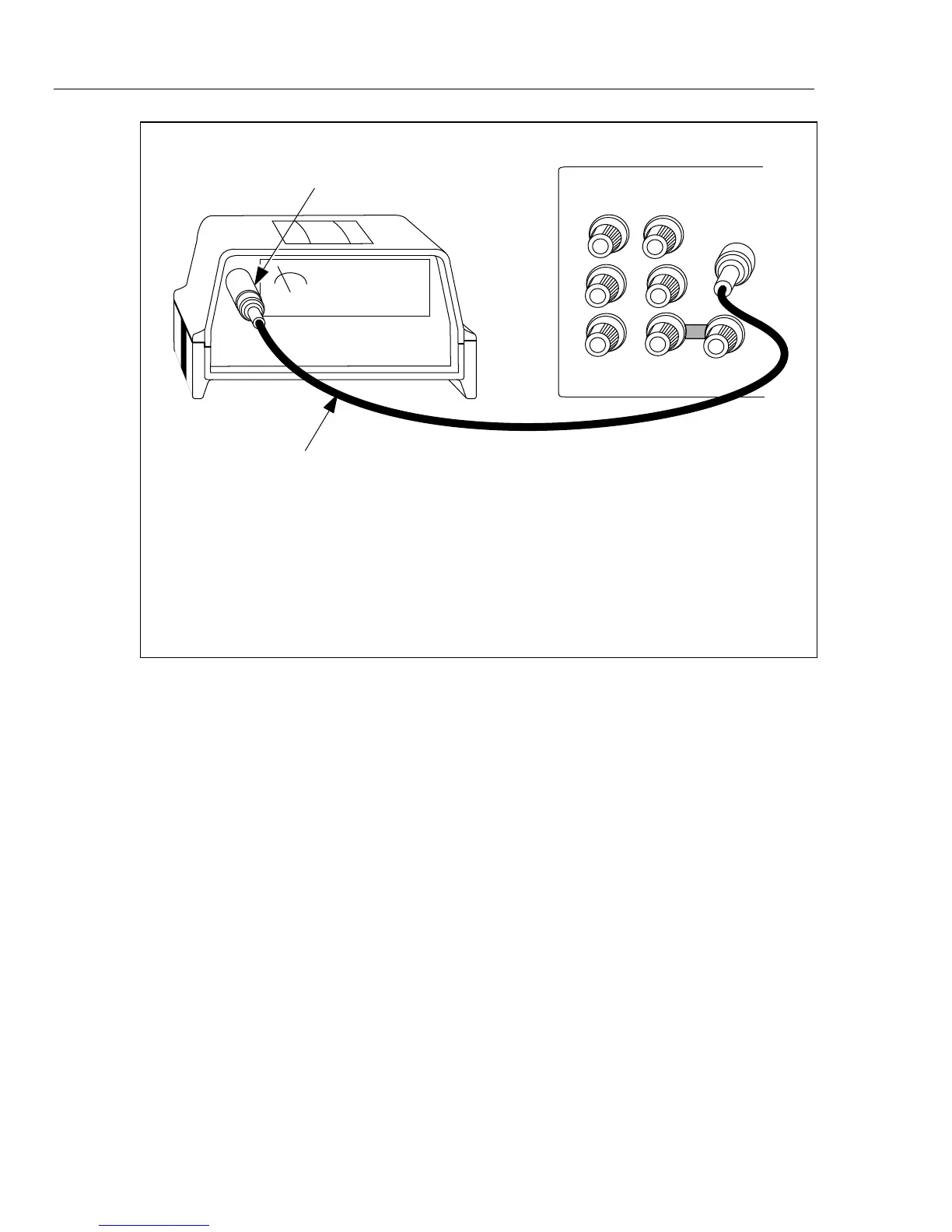
WIDEBAND
CABLE SUPPLIED WITH
OPTION 5700A-03
For wideband meters with higher than 50 input impedence, use
the 50 feedthrough terminator at the meter connection end.
For all wideband applications, take care to achieve a good 50
impedence match (use cable and connectors with a characteristic input
impedence of 50 ).
NOTE
Ω
Ω
Ω
Ω
Ω
Ω
50 FEEDTHROUGH TERMINATOR
SUPPLIED WITH OPTION 5700A-03
Ω
CALIBRATOR
Figure 4-5. UUT Wideband AC Voltage Output (Option 5700A-03)
4-24. Setting the Output
To set the output, simply press the following sequence of keys to select an output
function and amplitude:
[numeric keys]
→ [multiplier] → [function] → E → P
For example, to set the output to 10 mV dc, press:
1 0 m V EO
To set an ac output, press the following additional keys:
[numeric keys]
→ [multiplier] → H → E
For example, to change the present 10 mV dc to 10 mV ac at 1.8 kHz, press:
1 . 8 K H E
To change the output back to dc, simply press:
0 H E, or
+ E