5700A/5720A Series II
Operators Manual
4-24
4-25. DC Voltage Output
To set a dc voltage output, proceed as follows:
1. Make sure the calibrator is in standby (STANDBY annunciator lit). Press O if
necessary.
2. If the UUT is not connected, connect it now as described earlier in this chapter under
“Connecting the Calibrator to a UUT.”
3. Set the UUT to measure dc voltage on the appropriate range.
4. Press up to eight numeric keys to select a voltage.
5. To change the polarity of your entry, press +.
6. Press U, m, or K if necessary.
7. Press V.
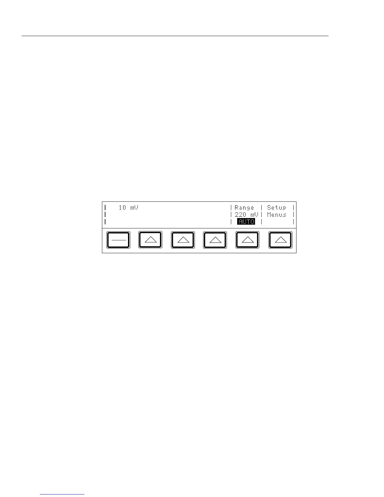
8. The Control Display now shows the amplitude of your entry. If you made an entry
error, press C to clear the display, then reenter the value. The following illustration
of the Control Display assumes an entry of 10 mV:
PREV
MENU
9. Press E. The calibrator clears your entry from the Control Display and copies
it into the Output Display. No voltage is available at the output terminals, however,
until you press O.
10. Press O to activate the calibrator’s output. The UUT will now respond to the
applied voltage.
Two softkey labels appear on the Control Display in the dc voltage function: “Range”
and “Setup Menus.”
• The “Range” softkey selects autorange or lock for the present range. When the range
is set to AUTO (the default setting), the calibrator automatically selects the lowest
possible range. The minimum output on all ranges except the 1100V range is 0V. The
minimum output on the 1100V range is 100V.
• The “Setup Menus” softkey opens the setup menu.