EasyManuals Logo

Fluke 5700A Series II User Manual

Fluke 5700A Series II
336 pages
To Next Page IconTo Next Page
To Previous Page IconTo Previous Page
Page #135 background imageLoading...
Page #135 background image
Front Panel Operation
Setting Output Limits 4
4-49
The 10.000208V output setting is calculated by the calibrator using the following
equation:
1
19 9 19 903
19 9
..
.
VV
V
= 1.0001508
This is applied to 10V to yield the following:
10V x 1.0001508 = 10.001508V
The 1.3 mV zero offset is then subtracted:
10.001508V 0.0013V = 10.000208V
8.
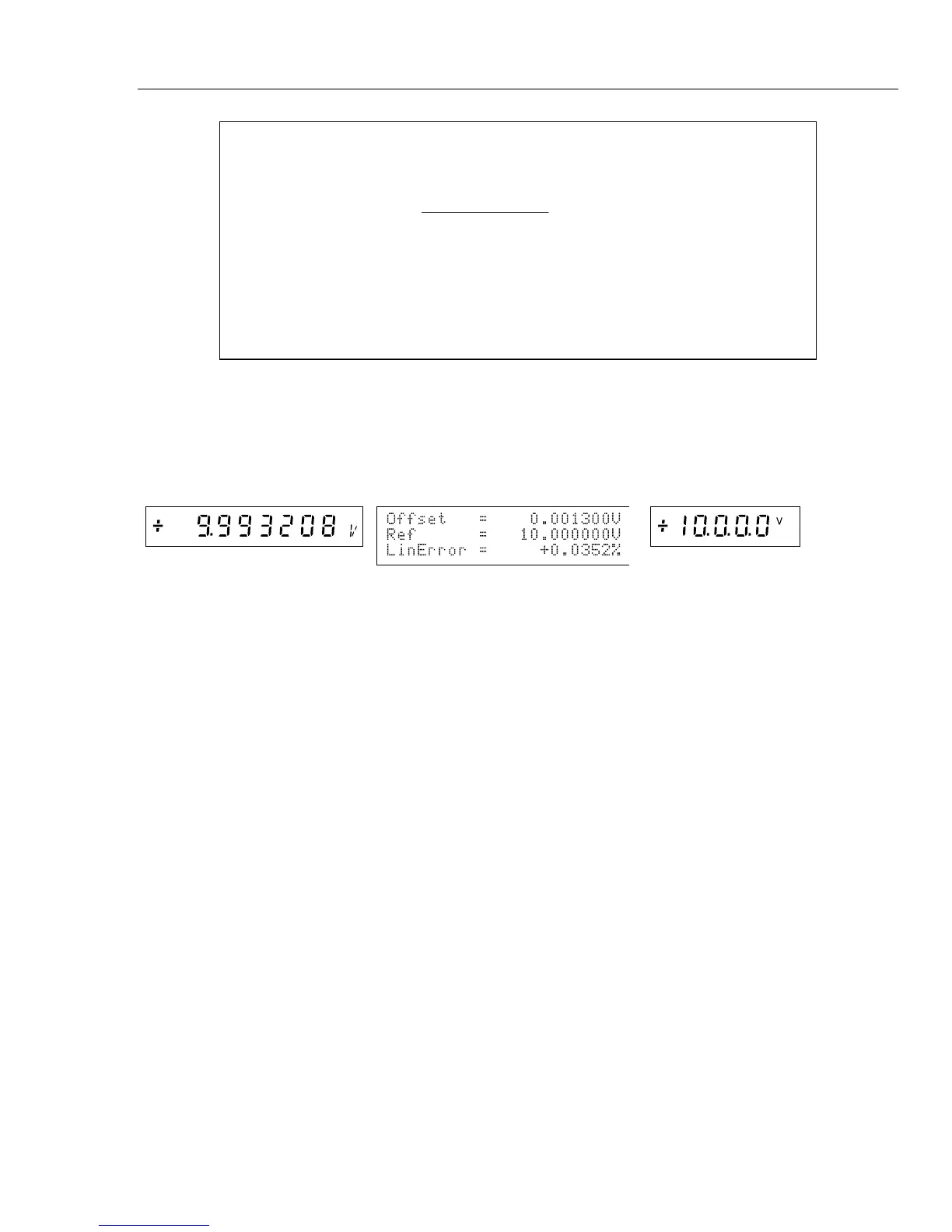
Use the output adjustment controls to adjust the calibrator’s output for a reading of
10.0V (the reference value) on the DMM. The displays change to:
Output Display
Control Display
UUT (DMM) Display
The Control Display now shows that the DMM scale error at 19.9V is -0.0151%, and the
DMM linearity error at 10V is +0.0352%.

Table of Contents

Other manuals for Fluke 5700A Series II

Questions and Answers:

Question and Answer IconNeed help?

Do you have a question about the Fluke 5700A Series II and is the answer not in the manual?

Fluke 5700A Series II Specifications

General IconGeneral
TypeMultifunction Calibrator
Operating Temperature0 °C to 50 °C
Storage Temperature-20 °C to 70 °C
Voltage Range0 to 1100 V
DC Voltage Range10 μV to 1100 V
Frequency Range1 MHz
Humiditynon-condensing
Power Requirements100 V to 240 V

Related product manuals