Front Panel Operation
Sample Applications 4
4-55
Note
The adjustment for calibrating the meter requires disassembling the meter.
Refer to the diagrams and access procedures in the
70 Series Service
Manual.
1. Verify that the calibrator is set to 0V dc in standby. Press r if it is not.
2.
Turn on the meter, and set its function switch to dcV.
3.
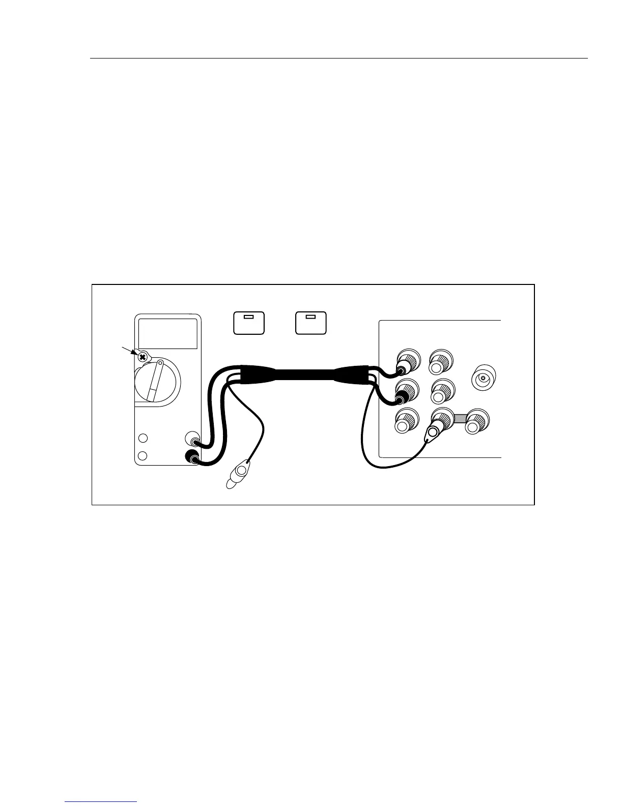
Connect a set of test leads to the meter as shown in Figure 4-12.
4.
Set the calibrator to 3V dc and press O.
5.
Adjust R8 (located just to the left of the rotary switch on the pca) in the meter for a
display reading of +3.00V dc ±.001V.
6.
Press r on the calibrator. Disconnect and turn off the meter. Calibration is
complete.
HI
HI
LO
LO
HI
AUX
CURRENT
GUARD GROUND
WIDEBAND
10A
300mA
V
COM
UUT
NC
R8
EX SNS
: OFF
EX GRD
: OFF
OUTPUT
V A
Ω
SENSE
V
Ω
Ω
CALIBRATOR
Figure 4-12. Cable Connections for Calibrating a Fluke 70 Series Multimeter