EasyManuals Logo

Fluke 5700A Series II User Manual

Fluke 5700A Series II
336 pages
To Next Page IconTo Next Page
To Previous Page IconTo Previous Page
Page #257 background imageLoading...
Page #257 background image
Operator Maintenance
Range Calibration 7
7-15
3. Press the “Range Adjust” softkey to bring up the next menu shown below:
PREV
MENU
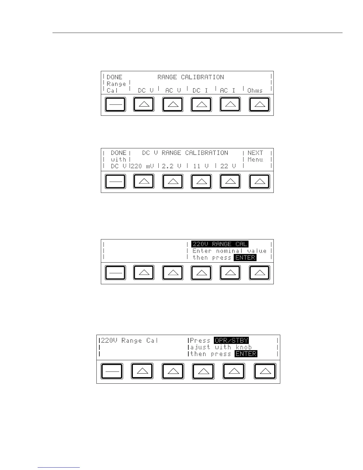
4. Press the “DC V” softkey to bring up the next menu shown below:
PREV
MENU
5. Press the “NEXT Menu” softkey, which scrolls through all the available dc voltage
ranges, until 220V appears. Then press that selection’s softkey to open a display
similar to the following:
PREV
MENU
6. Connect the 732B, 845A, and 732B in a 10:1 configuration, as shown in Figure 7-5.
7. Multiply the 732B’s value by 10, and enter this new value. (This value is the output
of the 752A, to which you will null the calibrator’s output.) Then press E to
bring up the following display.
PREV
MENU

Table of Contents

Other manuals for Fluke 5700A Series II

Questions and Answers:

Question and Answer IconNeed help?

Do you have a question about the Fluke 5700A Series II and is the answer not in the manual?

Fluke 5700A Series II Specifications

General IconGeneral
TypeMultifunction Calibrator
Operating Temperature0 °C to 50 °C
Storage Temperature-20 °C to 70 °C
Voltage Range0 to 1100 V
DC Voltage Range10 μV to 1100 V
Frequency Range1 MHz
Humiditynon-condensing
Power Requirements100 V to 240 V

Related product manuals