Analog Interface:
By entering a value between 0 and 10 V using an analog method, the arc length is cor-
rected, but the wire speed is not changed.
Value range Designation Min./max. possible value
0 V Arc length correction -10% = shorter arc
5 V Arc length correction 0% = saved value
10 V Arc length correction +10% = longer arc
Additional information for TWIN systems:
It is not possible to enter an analog set value on TWIN systems.
Job correction (specifications apply for Single- andTWIN welding):
- Factor = 10
- Data type SINT
- Specified as absolute value. Example: 1.5 = 150 step change
Pulse-/ dynamic
correction (Pulse/
dynamic correc-
tion) - Group
Input / Analog
Input
As described below, the value for the pulse/dynamic correction can be specified on a
Digital Interface or an Analog Interface.
The following specifications apply to the MIG/MAG standard synergic, MIG/MAG pulse
synergic, MIG/MAG PMC, and MIG/MAG LSC welding processes.
Digital Interface:
Entering a value between -32,768 and +32,767 (SINT 16) specifies the pulse/dynamic
correction, the wire speed is not changed.
Value range Designation Min./max. possible value
-32,768 Pulse/dynamic correction -10% = pulse/dynamic correction
0 Pulse/dynamic correction 0% = saved value
+32,767 Pulse/dynamic correction +10% = pulse/dynamic correction
Additional information for TWIN systems:
The digital set value must be entered separately for both power sources.
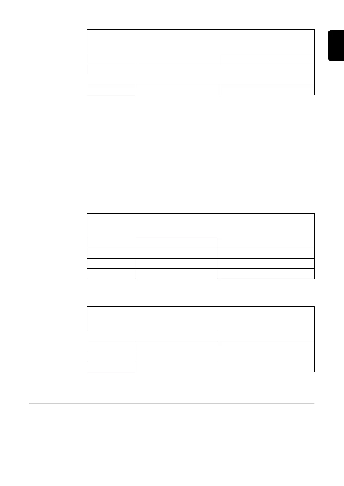
Analog Interface:
Entering a value between 0 and 10 V using an analog method specifies the pulse/
dynamic correction, the wire speed is not changed.
Value range Designation Min./max. possible value
0 V Pulse/dynamic correction -10% = pulse/dynamic correction
5 V Pulse/dynamic correction 0% = saved value
10 V Pulse/dynamic correction +10% = pulse/dynamic correction
Additional information for TWIN systems:
It is not possible to enter an analog set value on TWIN systems.
Wire retract cor-
rection (Wire
retraction correc-
tion) - Group
Input / Analog
Input
As described below, the value for the wire retraction correction can be specified on a
Digital Interface or an Analog Interface.
The following specifications apply to the MIG/MAG standard synergic, MIG/MAG pulse
synergic, MIG/MAG PMC, and MIG/MAG LSC welding processes.
21
EN-US