EasyManua.ls Logo

Fronius TPS/i User Manual

Fronius TPS/i
88 pages
To Next Page IconTo Next Page
To Previous Page IconTo Previous Page
Page #5 background imageLoading...
Page #5 background image
General
Data Types Used UINT 16 (Unsigned Integer) = Whole number in the range from 0 to 65,535
SINT 16 (Signed Integer) = Whole number in the range from -32,768 to 32,767
Conversion examples:
- For a positive value (SINT 16) = desired wire speed x factor = 12.3 m/min x 100 =
1230
dec
= 04CE
hex
- For a positive value (SINT 16) = desired arc length correction x factor = -6.4 x 10 =
-64
dec
= FFC0
hex
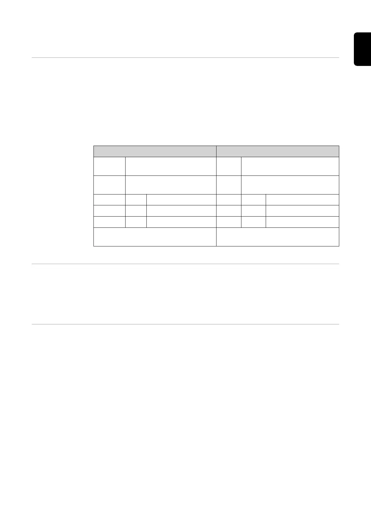
Unsigned (UINT): Signed (SINT):
Type: Unsigned 16 Bit integer = 16
bits
Type: Signed 16 Bit integer (15 bits +
1 Sign Bit*)
Range: 0 to 65535 Rang
e:
-32768 to 32767
0000 -10 (0000000000000000) 0000 0000 (0*000000000000000)
32767 0 (0111111111111111) 56 56 (0*000000000111000)
65535 +10 (1111111111111111) -64 -64 (1*111111111000000)
* = if the value entered has a negative
sign, the sign Bit is High – see markings
Behavior of the
Power Source
when an Interface
is Connected
If a power source from the TPS/i series is connected to a robot interface, the settings on
the power source remain unchanged (2-step mode, special 2-step mode, etc.).
If a power source from the TPS series is connected to a robot interface, the power
source automatically selects 2-step mode.
Availability of
Functions
As a result of updates, certain functions may be available on your device that are not
described in this document, or vice versa.
5
EN-US

Table of Contents

Question and Answer IconNeed help?

Do you have a question about the Fronius TPS/i and is the answer not in the manual?

Fronius TPS/i Specifications

General IconGeneral
BrandFronius
ModelTPS/i
CategoryWelding System
LanguageEnglish

Summary

General Information and Safety

Data Types Used

Defines UINT 16 and SINT 16 data types for signal representation.

Interface Connection Behavior

Explains power source response when connected to a robot interface.

Function Availability

Notes variations in function availability due to software updates.

Signal Transmission Time

Illustrates signal timing and transmission delays during operation.

Safety Information

Crucial warnings and safety procedures for correct operation.

Digital Inputs Overview

Basic Control Signals

Welding start, robot ready, and operating mode selection signals.

Process Control Inputs

Gas flow and wire feed/retraction control signals.

Sensing and Simulation Inputs

Touch sensing, simulation, and wire brake signals.

Configuration and Mode Inputs

Job, characteristic, and TWIN mode selection signals.

Analog Inputs

Wire Feed Speed and Corrections

Sets wire feed speed and adjusts arc length/dynamics.

WireSense Edge Detection

Scans component surfaces for precise edge detection.

Wire Length and Process Parameters

Specifies wire feed length and seam number.

Digital Outputs

System Status and Readiness

Reports power source status, warnings, and system readiness.

Welding Process State

Indicates active process, current flow, and robot motion release.

Arc and Signal Monitoring

Monitors arc stability and main current signals.

Output and Status Indicators

Signals for range deviations, process selection, and external outputs.

Related product manuals