Detailed descrip-
tion of Limit Mon-
itoring
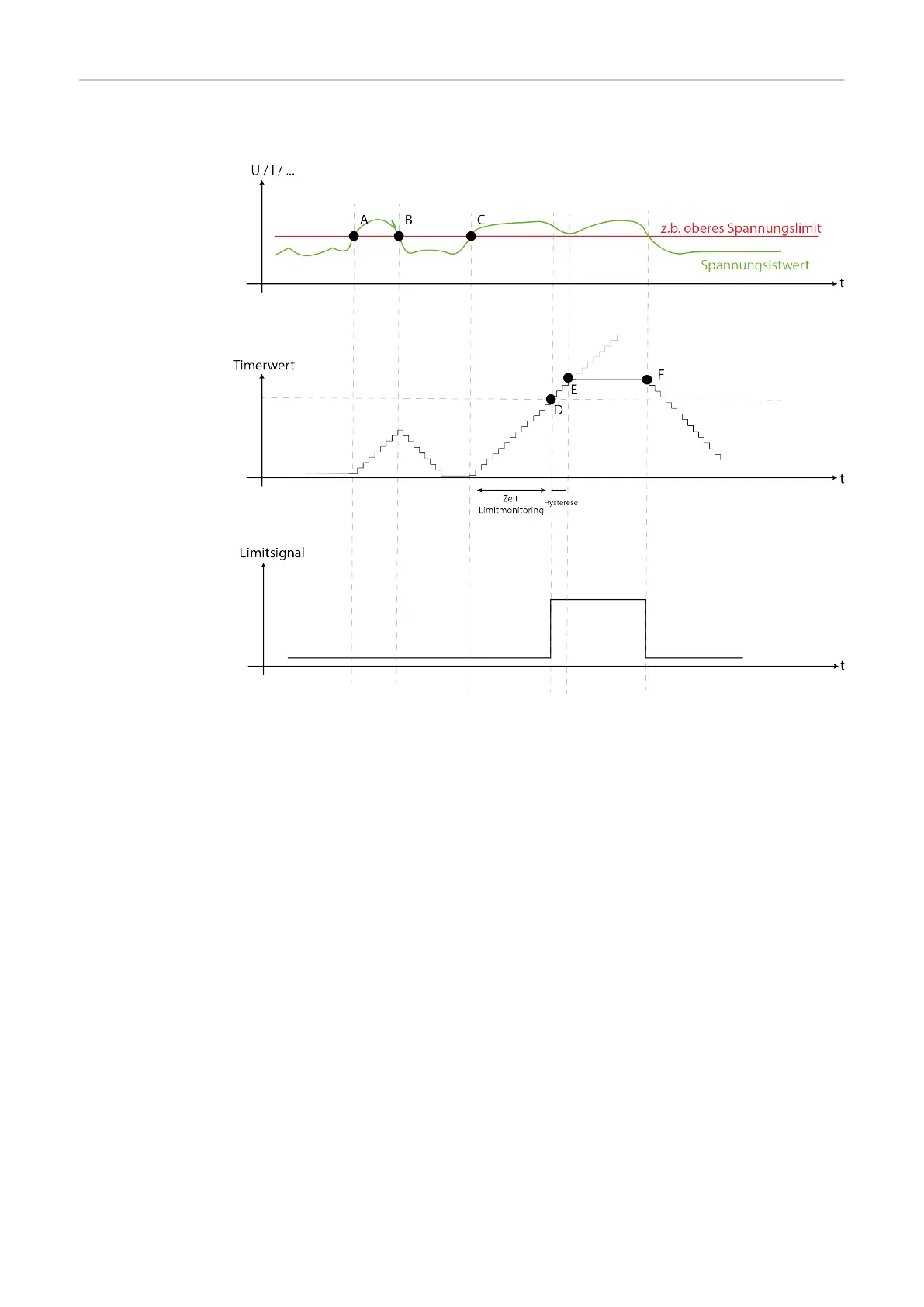
- Limit Monitoring is only active in the main current phase
- The data is recorded / checked every 50 ms during Limit Monitoring
- At point A, the upper voltage limit is exceeded; the time until the reaction of Limit
Monitoring begins to count constantly upwards
- At point B, the voltage falls below the upper limit again; the time until the reaction of
Limit Monitoring counts down to 0
- At point C, the upper voltage limit is exceeded again; the time until the reaction of
Limit Monitoring starts to count upwards constantly again
- At point D, the set time limit for the reaction of limit monitoring is reached
- The hysteresis time starts to run
- Point E shows the hysteresis of +20% to the set time value (time until reaction
from Limit Monitoring)
- A warning or an error is issued depending on the setting
- The Limitsignal (Word 1 / Byte 2 / Bit 19) changes to High
- At point F, the Limitsignal (Word 1 / Byte 2 / Bit 19) changes to Low
Functionality of Limit Monitoring for energy and welding duration:
- With energy monitoring, Limit Monitoring does not monitor each job individually, but
the entire weld seam - for more information see Energy monitoring from page 71
- With welding time monitoring, Limit Monitoring does not monitor each job individu-
ally, but the entire weld seam - for more information, see Welding time monitoring
from page 69
66