Value range Min./max. possible value
-32,768 1 mm (0.039 inches)
+32,767 10,000 mm (393.7 inches)
Additional information for TWIN systems:
The digital set value must be entered separately for both power sources.
Analog Interface:
The set value for the length of wire to be fed is specified by entering an analog value
of 0 to 10 V.
Value range Min./max. possible value
0 V 1 mm (0.039 inches)
10 V 10,000 mm (393.7 inches)
Additional information for TWIN systems:
It is not possible to enter an analog set value on TWIN systems.
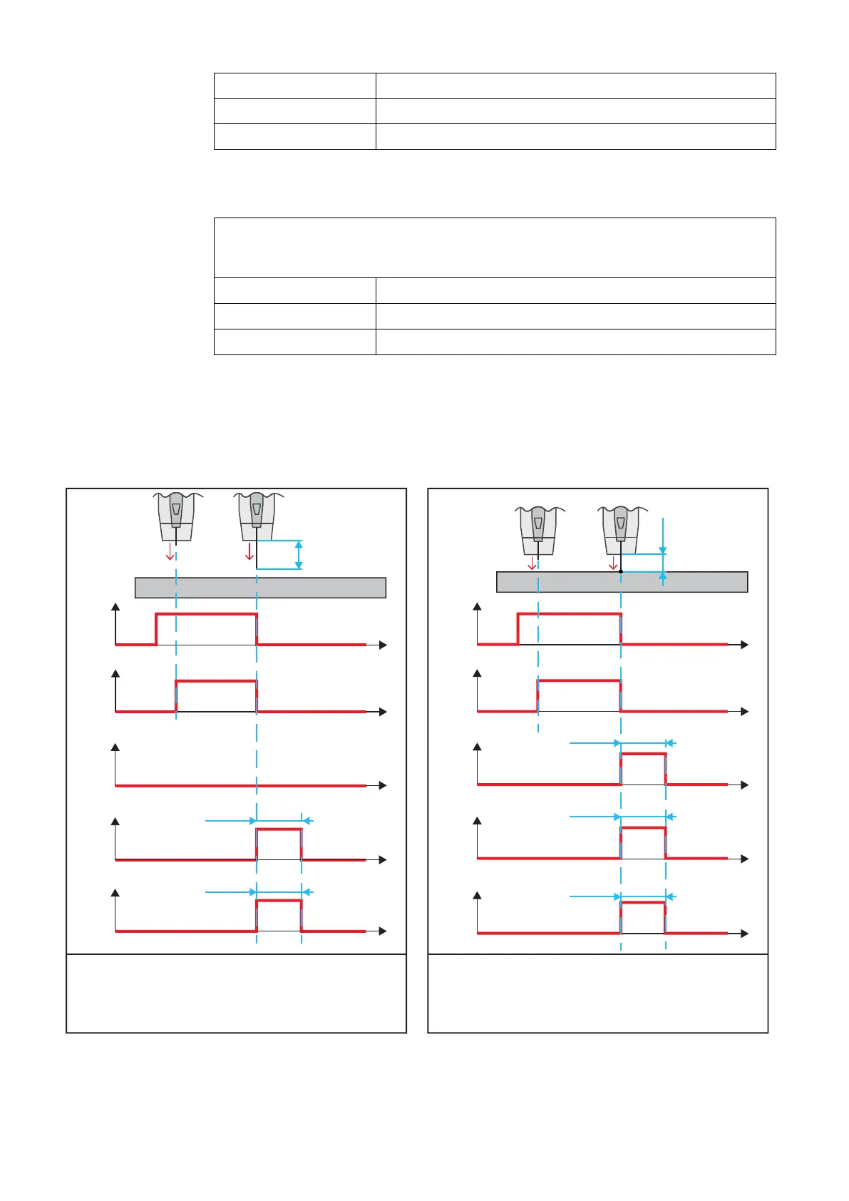
Signal course - set Wire forward length (= 25
mm / 0.984 inches) could be reached according
to plan:
Signal course - workpiece contact occurs
before the set Wire forward length (= 25 mm /
0.984 inches) could be reached:
1 Second
1 Second
1
2
3
4
1 = Wire forward / backward length (Analog Input) | Bit 240 - 255
2 = Wire forward (Digital Input) | Bit 9
3 = Arc stable / Touch signal (Digital Output) | Bit 5
4 = Touch signal (Digital Input) | Bit 7
5 = WireSense Position (Analog Output) | Bit 256 - 271
t
t
t
t
5
t
25 mm
(0.984 inch)
t
t
t
1
2
3
4
5
1 = Wire forward / backward length (Analog Input) | Bit 240 - 255
2 = Wire forward (Digital Input) | Bit 9
3 = Arc stable / Touch signal (Digital Output) | Bit 5
4 = Touch signal (Digital Input) | Bit 7
5 = WireSense Position (Analog Output) | Bit 256 - 271
t
1 Second
15 mm
(0.591 inch)
t
1 Second
1 Second
24