5-2
MHT260a (Engl.)
The signal form of the [START] and the current position output varies depending on the upper level interface.
Auto start
Current position output
Amplifier Current position output
Basic type (DI/DO position) Current position can be outputted.
SX bus type (SX bus direct connection) Current position can be outputted to IQ area.
T-link type (T-link direct connection) Current position can be outputted to WB area.
5.2 Run command
This section explains the signals to run the motor and the signals to reset alarm detection.
Control input signal :・Run command [RUN] (1) Control output signal : ・Ready [RDY] ( 1)
・Alarm reset [RST] (11) ・CPU ready [CPURDY] (28)
・Alarm detection [ALM] (16)
・Alarm code 0 [ALM0] (32)
・Alarm code 1 [ALM1] (33)
・Alarm code 2 [ALM2] (34)
・Alarm code 3 [ALM3] (35)
・Alarm code 4 [ALM4] (36)
5.2.1 Run command [RUN]
The signal allows the motor to rotate.
Run command [RUN] (Control input signal)
■ Function
While the [RUN] signal is on, the motor is powered on and can rotate.
Even if commercial power is applied to amplifier, the motor will not start running while [RUN] is off.
When turning off this [RUN] signal while motor is running, motor decelerates quickly until it stops. After the stoppage, it is not held. No
holding torque is available after the motor stops.
While the [RUN] signal is turned off, all rotational commands are ignored.
Basically, motor can be rotated when [RUN] is on and the forced stop [EMG] signal is on.
While the [RUN] signal is on and other signals are off, the motor is in stopping condition.
Amplifier Setting of position data
Basic type (DI/DO position) Sets the data of specified station as the control input.
SX bus type (SX bus direct connection) Writes the data of the specified station and the speed into IQ area.
T-link type (T-link direct connection) Writes the data of the specified station into WB area.
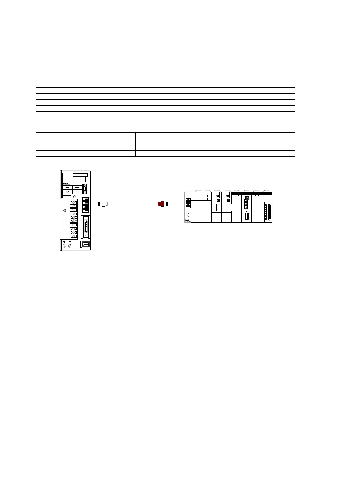
SXbus extension cable
K80791234
K80791234K80791234
K80791234
L1
L1L1
L1
L2
L2L2
L2
L3
L3L3
L3
DB
DBDB
DB
P1
P1P1
P1
N
NN
N
P+
P+P+
P+
U
UU
U
V
VV
V
W
WW
W
CHARGE
CHARGECHARGE
CHARGE
FALDIC
FALDICFALDIC
FALDIC
SHIFT
SHIFTSHIFT
SHIFT
ENT
ENTENT
ENT
RYS201S3-LSS
RYS201S3-LSSRYS201S3-LSS
RYS201S3-LSS
MODE
MODEMODE
MODE
ESC
ESCESC
ESC
APS30
APS30APS30
APS30
PWR
PWRPWR
PWR
ALM
ALMALM
ALM
SX
SXSX
SX
SCPU32
SCPU32SCPU32
SCPU32
LOADER
LOADERLOADER
LOADER
RUN
RUNRUN
RUN
TERM
TERMTERM
TERM
SLV
SLVSLV
SLV
STOP
STOPSTOP
STOP
CPU
CPUCPU
CPU
No.
No.No.
No.
ONL
ONLONL
ONL
ERR
ERRERR
ERR
RUN
RUNRUN
RUN
ALM
ALMALM
ALM
BAT
BATBAT
BAT
ONL01234567
ONL01234567ONL01234567
ONL01234567
ERR89101112131415
ERR89101112131415ERR89101112131415
ERR89101112131415
ONLCH1
ONLCH1ONLCH1
ONLCH1
ERRCH2
ERRCH2ERRCH2
ERRCH2
EMG+OT‑OT
EMG+OT‑OTEMG+OT‑OT
EMG+OT‑OT
20
2020
20
1
11
1
B/A
B/AB/A
B/A
HP2
HP2HP2
HP2
ONL
ONLONL
ONL
ERR
ERRERR
ERR
PE1
PE1PE1
PE1
PH
PHPH
PH
PL
PLPL
PL
DA
DADA
DA
CH
CHCH
CH
No.
No.No.
No.
SCPU32
SCPU32SCPU32
SCPU32
LOADER
LOADERLOADER
LOADER
RUN
RUNRUN
RUN
TERM
TERMTERM
TERM
SLV
SLVSLV
SLV
STOP
STOPSTOP
STOP
CPU
CPUCPU
CPU
No.
No.No.
No.
ONL
ONLONL
ONL
ERR
ERRERR
ERR
RUN
RUNRUN
RUN
ALM
ALMALM
ALM
BAT
BATBAT
BAT
ONL01234567
ONL01234567ONL01234567
ONL01234567
ERR89101112131415
ERR89101112131415ERR89101112131415
ERR89101112131415
 Loading...


