CHAPTER 4
ETSI Configuration
Installing Power and Ground Cables
4-63
FLASHWAVE 7500 Release 6.1
Equipment Installation
Fujitsu and Fujitsu Customer Use Only
FNC-7500-0061-200
Issue 1, May 2009
Figure 4-46 [p. 4-64] shows the Optical/Tributary shelf station interface area (SIA), and
Figure 4-47 [p. 4-65] shows the power cabling.
Note: The PDP has dual-post output power connectors.
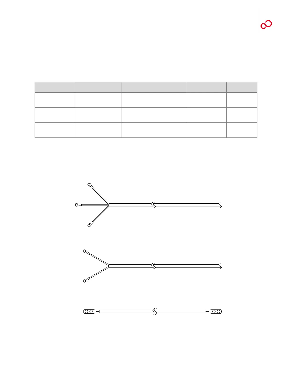
Table 4-2: Power and Ground Cable Connections
(ETSI Configuration)
Part Number Use Description Term Type Wire Gauge
PC660-0105-T019 –48 V DC and ground 3-wire rack/shelf power and frame
ground harness, one set per shelf
10 AWG crimp
lugs
10 AWG
PC660-0105-T020 –48 V DC and ground 2-wire rack/shelf power harness,
one set per shelf
10 AWG crimp
lugs
10 AWG
PC660-0105-T021 Frame ground Frame ground stranded wire cable
from rack to PDP, one per rack
Te r m i na l l u g s ,
both ends, installed
6 AWG,
stranded
Figure 4-44: ETSI Power and Ground Cables
FGND
G A
M A
G B
M B
Green/Yellow
Blue
Gray
Blue/White
Gray/White
Green/Yellow
Frame Ground Cable (PC660-0105-T021)
Rack/Shelf Power Harness (PC660-0105-T020)
Rack/Shelf Power Harness (PC660-0105-T019)
m1718rw_1