CHAPTER 5
Extension Configuration
Installing Cables
5-57
FLASHWAVE 7500 Release 6.1
Equipment Installation
Fujitsu and Fujitsu Customer Use Only
FNC-7500-0061-200
Issue 1, May 2009
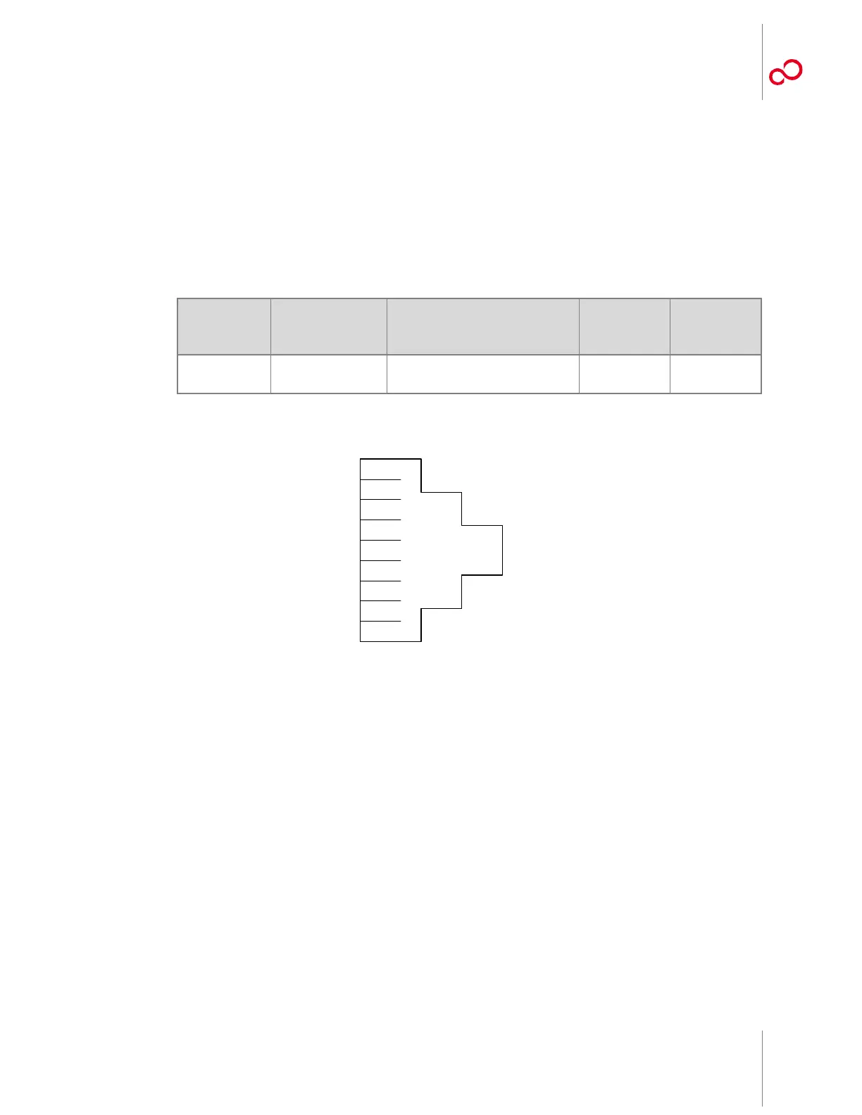
5.13.7 Installing OSS Cable
This procedure provides instructions for assembling the OSS cable and installing it on the
Extension shelf backplane (CN11). Table 5-6 [p. 5-57] lists pertinent information for this
cable. Figure 5-27 [p. 5-57] shows the cable connector pinouts.
1 Connect the cable to shelf backplane connector CN11 (see Figure 5-22 [p. 5-49]).
2 Connect the other end of the cable to the appropriate router or hub.
Note: The 21-094-xxx cable can also be used to connect a PC to the TERM2 Ethernet port on the
Extension shelf front panel.
Note: The OSS port has automatic cable-detect capability to properly function with both crossover
and straight cables.
This procedure is complete.
Table 5-6: OSS Cable Information
(Extension Configuration)
Cable Part
Number
Backplane
Connector
Number
Cable Description
Connector
Type
Cable Wire
Size
21-332-xxx or
21-094-xxx
a
a
xxx = length in feet
CN11 Ethernet connection 8-pin RJ-45 24 AWG
Figure 5-27: Connector Pinouts, OSS Cable
1
2
3
4
5
6
7
8
TXP
TXN
RXP
RXN
m1714au_1