GE Power Management 269Plus Motor Management Relay 4-
13
4 COMMUNICATIONS MEMORY MAP
4
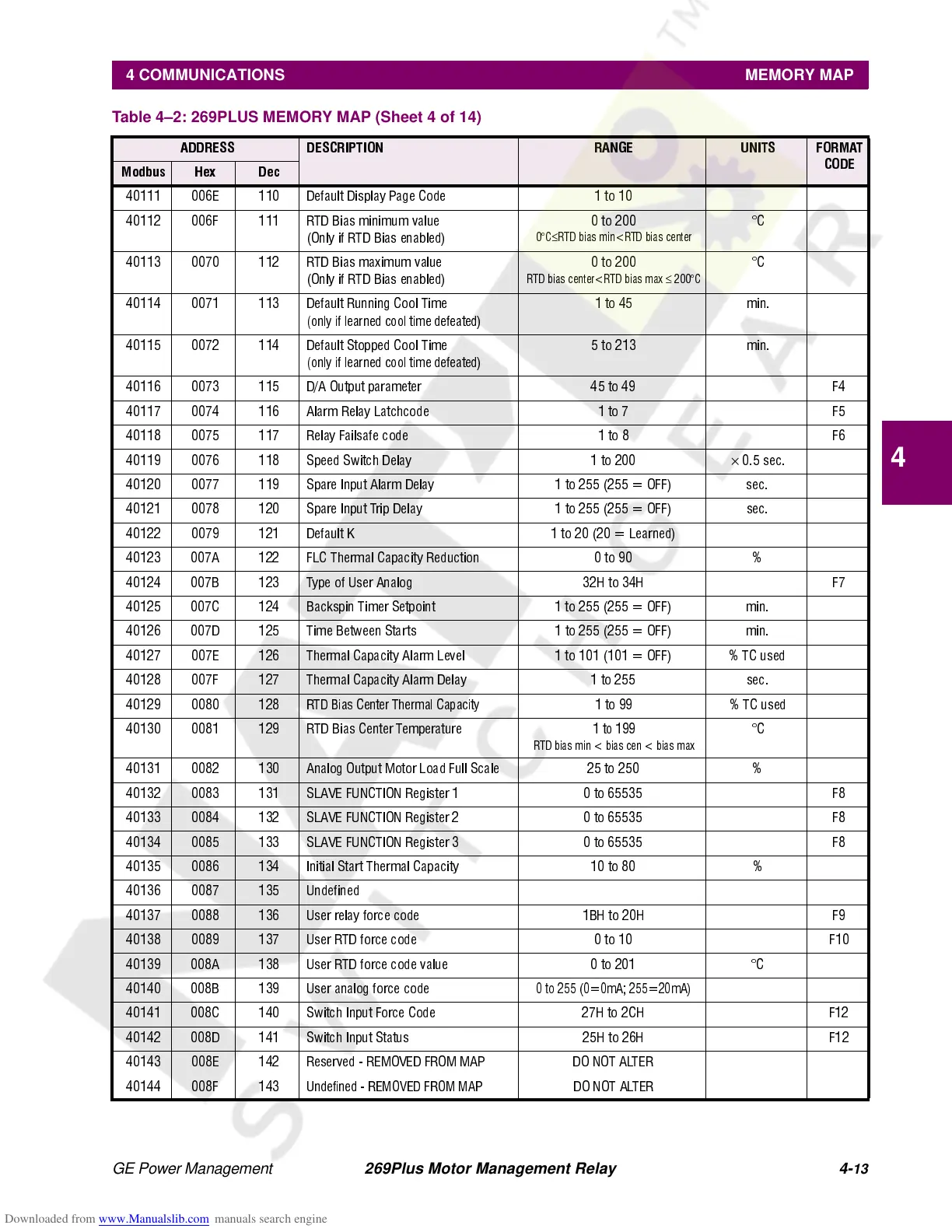
40111 006E 110 Default Display Page Code 1 to 10
40112 006F 111 RTD Bias minimum value
(Only if RTD Bias enabled)
0to200
0°C
≤
RTD bias min<RTD bias center
°C
40113 0070 112 RTD Bias maximum value
(Only if RTD Bias enabled)
0to200
RTD bias center<RTD bias max
≤
200°C
°C
40114 0071 113 Default Running Cool Time
(only if learned cool time defeated)
1 to 45 min.
40115 0072 114 Default Stopped Cool Time
(only if learned cool time defeated)
5 to 213 min.
40116 0073 115 D/A Output parameter 45 to 49 F4
40117 0074 116 Alarm Relay Latchcode 1 to 7 F5
40118 0075 117 Relay Failsafe code 1 to 8 F6
40119 0076 118 Speed Switch Delay 1 to 200
×
0.5 sec.
40120 0077 119 Spare Input Alarm Delay 1 to 255 (255 = OFF) sec.
40121 0078 120 Spare Input Trip Delay 1 to 255 (255 = OFF) sec.
40122 0079 121 Default K 1 to 20 (20 = Learned)
40123 007A 122 FLC Thermal Capacity Reduction 0 to 90 %
40124 007B 123 Type of User Analog 32H to 34H F7
40125 007C 124 Backspin Timer Setpoint 1 to 255 (255 = OFF) min.
40126 007D 125 Time Between Starts 1 to 255 (255 = OFF) min.
40127 007E 126 Thermal Capacity Alarm Level 1 to 101 (101 = OFF) % TC used
40128 007F 127 Thermal Capacity Alarm Delay 1 to 255 sec.
40129 0080 128
RTD Bias Center Thermal Capacity
1 to 99 % TC used
40130 0081 129 RTD Bias Center Temperature
1to199
RTD bias min < bias cen < bias max
°C
40131 0082 130 Analog Output Motor Load Full Scale 25 to 250 %
40132 0083 131 SLAVE FUNCTION Register 1 0 to 65535 F8
40133 0084 132 SLAVE FUNCTION Register 2 0 to 65535 F8
40134 0085 133 SLAVE FUNCTION Register 3 0 to 65535 F8
40135 0086 134 Initial Start Thermal Capacity 10 to 80 %
40136 0087 135 Undefined
40137 0088 136 User relay force code 1BH to 20H F9
40138 0089 137 User RTD force code 0 to 10 F10
40139 008A 138 User RTD force code value 0 to 201 °C
40140 008B 139 User analog force code
0 to 255 (0=0mA; 255=20mA)
40141 008C 140 Switch Input Force Code 27H to 2CH F12
40142 008D 141 Switch Input Status 25H to 26H F12
40143 008E 142 R eserved - REMOVED FROM MAP DO NOT ALTER
40144 008F 143
Undefined - REMOVED FROM MAP
DO NOT ALTER
Table 4–2: 269PLUS MEMORY MAP (Sheet 4 of 14)
ADDRESS DESCRIPTION RANGE UNITS FORMAT
CODE
Modbus Hex Dec