4-
28
269Plus Motor Management Relay GE Power Management
FORMAT CODES 4 COMMUNICATIONS
4
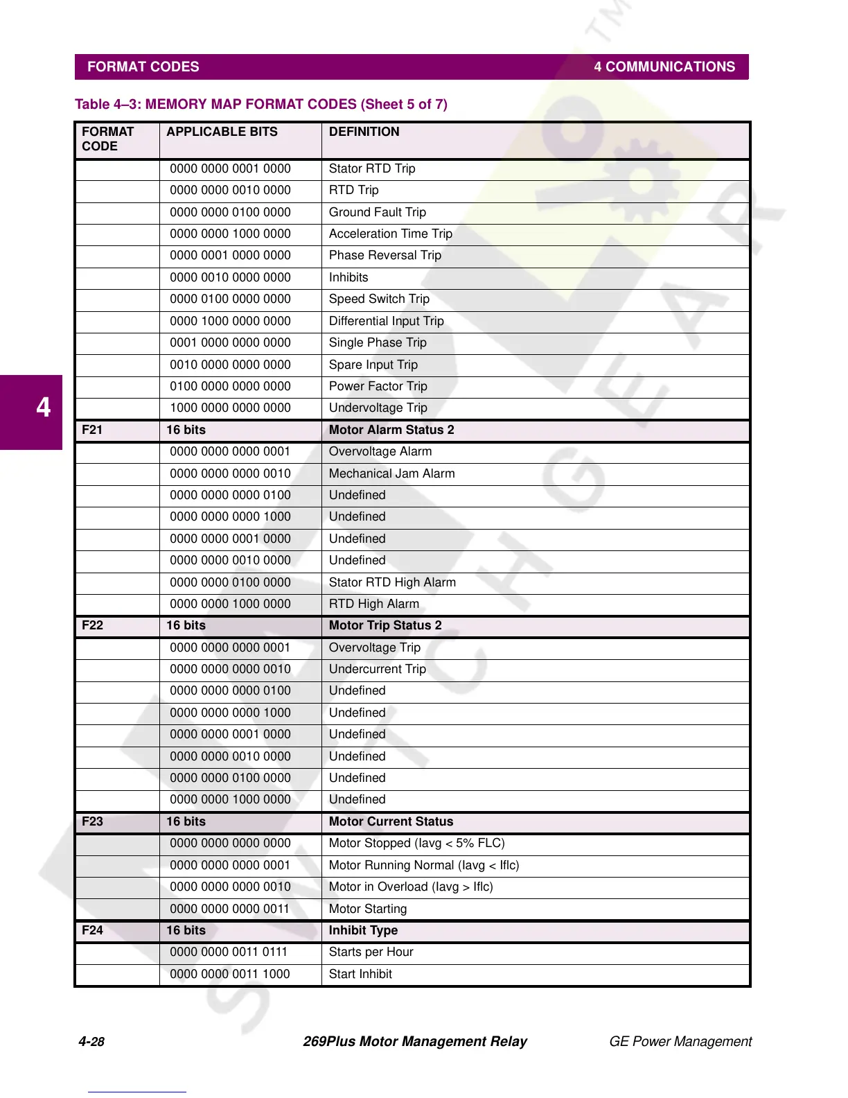
0000 0000 0001 0000 Stator RTD Trip
0000 0000 0010 0000 RTD Trip
0000 0000 0100 0000 Ground Fault Trip
0000 0000 1000 0000 Acceleration Time Trip
0000 0001 0000 0000 Phase Reversal Trip
0000 0010 0000 0000 Inhibits
0000 0100 0000 0000 Speed Switch Trip
0000 1000 0000 0000 Differential Input Trip
0001 0000 0000 0000 Single Phase Trip
0010 0000 0000 0000 Spare Input Trip
0100 0000 0000 0000 Power Factor Trip
1000 0000 0000 0000 Undervoltage Trip
F21 16 bits Motor Alarm Status 2
0000 0000 0000 0001 Overvoltage Alarm
0000 0000 0000 0010 Mechanical Jam Alarm
0000 0000 0000 0100 Undefined
0000 0000 0000 1000 Undefined
0000 0000 0001 0000 Undefined
0000 0000 0010 0000 Undefined
0000 0000 0100 0000 Stator RTD High Alarm
0000 0000 1000 0000 RTD High Alarm
F22 16 bits Motor Trip Status 2
0000 0000 0000 0001 Overvoltage Trip
0000 0000 0000 0010 Undercurrent Trip
0000 0000 0000 0100 Undefined
0000 0000 0000 1000 Undefined
0000 0000 0001 0000 Undefined
0000 0000 0010 0000 Undefined
0000 0000 0100 0000 Undefined
0000 0000 1000 0000 Undefined
F23 16 bits Motor Current Status
0000 0000 0000 0000 Motor Stopped (Iavg < 5% FLC)
0000 0000 0000 0001 Motor Running Normal (Iavg < Iflc)
0000 0000 0000 0010 Motor in Overload (Iavg > Iflc)
0000 0000 0000 0011 Motor Starting
F24 16 bits Inhibit Type
0000 0000 0011 0111 Starts per Hour
0000 0000 0011 1000 Start Inhibit
Table 4–3: MEMORY MAP FORMAT CODES (Sheet 5 of 7)
FORMAT
CODE
APPLICABLE BITS DEFINITION