3-
24
269Plus Motor Management Relay GE Power Management
SETPOINTS MODE 3 SETUP AND USE
3
232
SETPOINTS PAGE 3: O/L CURVE SETPOINTS
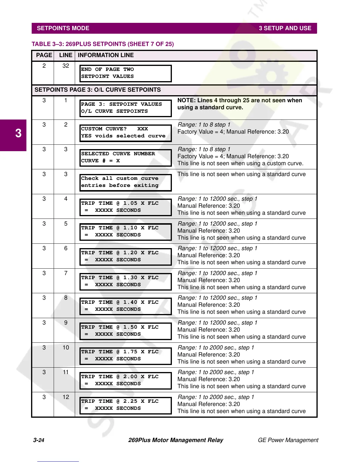
31 NOTE: Lines 4 through 25 are not seen when
using a standard curve.
32
Range: 1 to 8 step 1
Factory Value = 4; Manual Reference: 3.20
33
Range: 1 to 8 step 1
Factory Value = 4; Manual Reference: 3.20
This line is not seen when using a custom curve.
3 3 This line is not seen when using a standard curve
34
Range: 1 to 12000 sec., step 1
Manual Reference: 3.20
This line is not seen when using a standard curve
35
Range: 1 to 12000 sec., step 1
Manual Reference: 3.20
This line is not seen when using a standard curve
36
Range: 1 to 12000 sec., step 1
Manual Reference: 3.20
This line is not seen when using a standard curve
37
Range: 1 to 12000 sec., step 1
Manual Reference: 3.20
This line is not seen when using a standard curve
38
Range: 1 to 12000 sec., step 1
Manual Reference: 3.20
This line is not seen when using a standard curve
39
Range: 1 to 12000 sec., step 1
Manual Reference: 3.20
This line is not seen when using a standard curve
310
Range: 1 to 2000 sec., step 1
Manual Reference: 3.20
This line is not seen when using a standard curve
311
Range: 1 to 2000 sec., step 1
Manual Reference: 3.20
This line is not seen when using a standard curve
312
Range: 1 to 2000 sec., step 1
Manual Reference: 3.20
This line is not seen when using a standard curve
TABLE 3–3: 269PLUS SETPOINTS (SHEET 7 OF 25)
PAGE LINE INFORMATION LINE
END OF PAGE TWO
SETPOINT VALUES
PAGE 3: SETPOINT VALUES
O/L CURVE SETPOINTS
CUSTOM CURVE? XXX
YES voids selected curve
SELECTED CURVE NUMBER
CURVE#=X
Check all custom curve
entries before exiting
TRIP TIME @ 1.05 X FLC
= XXXXX SECONDS
TRIP TIME @ 1.10 X FLC
= XXXXX SECONDS
TRIP TIME @ 1.20 X FLC
= XXXXX SECONDS
TRIP TIME @ 1.30 X FLC
= XXXXX SECONDS
TRIP TIME @ 1.40 X FLC
= XXXXX SECONDS
TRIP TIME @ 1.50 X FLC
= XXXXX SECONDS
TRIP TIME @ 1.75 X FLC
= XXXXX SECONDS
TRIP TIME @ 2.00 X FLC
= XXXXX SECONDS
TRIP TIME @ 2.25 X FLC
= XXXXX SECONDS