GE Energy
D20/D200
Installation and Operations Guide
General 994-0078-2.00-7
Full
115
Operation
D20ME/ME II
Main Board
The front panel has four LED indicators, providing a visual indication of the
operational status of the unit:
• ALARM: LED is not implemented
• FAIL: driven by a programmed signal. Indicates that diagnostics are running or
have failed
• HALT: driven by the halt line input of the microprocessor. Indicates that MPU
has stopped
• RUN: driven by the address strobe line on the microprocessor. Indicates any
microprocessor activity
I/O Peripherals
Common LEDS
The WESDAC/WESTERM Peripheral pairs have a common section made up of
components on the WESDAC and WESTERM boards. There are seven LED
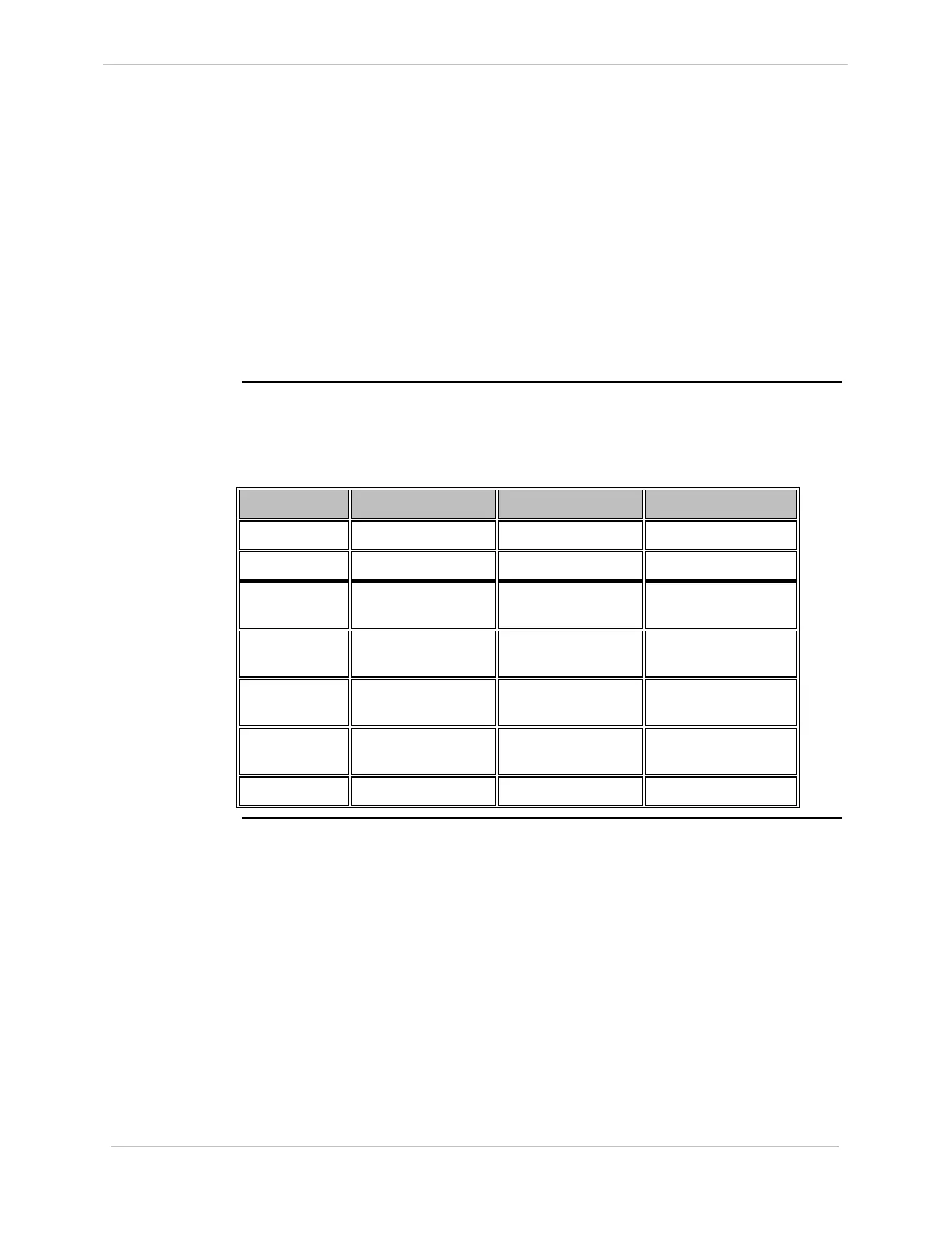
indicators on this common section.
LED Name Designation Normal RUN Not Initialized
DS1 Power On On On
DS2 MPU Run Flash 10/sec See Next Table
DS3 Tx1 Flickers Constantly Depends on Nature of
Fault
DS4 Rx1 Flickers Constantly Depends on Nature of
Fault
DS5 Tx2 Configuration
Dependent
Depends on Nature of
Fault
DS6 Rx2 Configuration
Dependent
Depends on Nature of
Fault
DS7 Fault Off See Next Table