D20/D200
Installation and Operations Guide
GE Energy
994-0078-2.00-7 General
72
Full
Connections and Configuration, continued
WESTERM
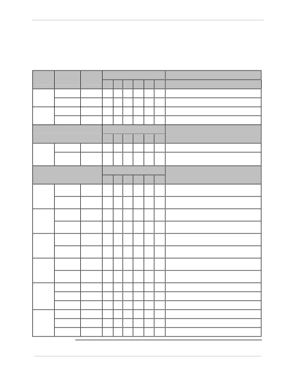
D20C: Settings
The following table gives jumper settings for Z2 to Z20.
Option 1 Jumper Definition – Status Jumper
Number
Jumper
Position
Jumper
Setting
1A 1B 1C 1D
1 – 2 IN
√
√
D20 Peripheral DC Supply Voltage Z2 & Z3
2 – 3 IN
√
√
External DC Supply Voltage on TB1 – 1 & 51
1 – 2, 3 – 4 IN
√ √
Contact Wetting Configuration Z19 &
Z20
2 – 3 IN
√ √
Group Common Configuration
Option 2
2A 2B
Jumper Definition – Control Wetting
Source/Relay Common
1 – 2 IN
√
Internal Control Common Supplied on TB1 – 2 Z4 & Z17
2 – 3 IN
√
External Control O/P Voltage Source to be Supplied
on TB1 – 2
Option 3
3A 3B 3C 3D 3E 3F
Jumper Definition – Control O/P
Configuration
1 – 2 IN
√
√ √ √ √
Master T/C source to C control O/P
1 & 2 = (T/C 1 & 2)
Z5
2 – 3 IN
√
R/L source to C control O/P
1 & 2 = (R/L 4)
1 – 2 IN
√
√ √
√
Master T/C source to C control O/P
3 & 4 = (T/C 3 & 4)
Z6
2 – 3 IN
√
√
R/L source to C control O/P
3 & 4 = (R/L 3)
1 – 2 IN
√
√
√
Master T/C source to C control O/P
5 & 6 = (T/C 5 & 6)
Z7
2 – 3 IN
√
√ √
R/L source to C control O/P
5 & 6 = (R/L 2)
1 – 2 IN
√
√
Master T/C source to C control O/P
7 & 8 = (T/C 7 & 8)
Z8
2 – 3 IN
√ √ √ √
R/L source to C control O/P
7 & 8 = (R/L 1)
1 – 2, 3 – 4 IN
√
√ √ √
T/C Configuration (T/C 1 & 2)
1 – 2 IN
√
R/L Configuration (R/L 4)
Z9 & Z13
2 – 3 IN
√
From C Control Outputs 1 & 2
1 – 2, 3 – 4 IN
√
√ √
T/C Configuration (T/C 3 & 4)
1 – 2 IN
√
√
R/L Configuration (R/L 3)
Z10 &
Z14
2 – 3 IN
√
Form C Control Outputs 3 & 4