GE Energy
D20/D200
Installation and Operations Guide
General 994-0078-2.00-7
Full
51
Connections and Configuration, continued
D20ME/ME II
Power
Connections
Power is supplied to the D20ME/ME II Main Boards through the backplane:
• WESTERM D20M+ SS for non-VME. See Module Layout 517-0224-ML
• WESTERM D20 VME bus backplane. See Module Layout 517-0123-ML
• SCHROFF VME bus backplane. See Module Layout 500-0307-ML
D200 Power
Supply
The D200 uses two power supply units, one for 5V and one for +12/-12V supply.
Power is supplied through the CCU Switch and Fuse Assembly. Each unit can be
switched to accommodate 110V or 220V mains power supply. There is also a
version with a 48 VDC input.
There may be two of each power supply for redundancy: two 5V and two +12/-12V.
Procedure
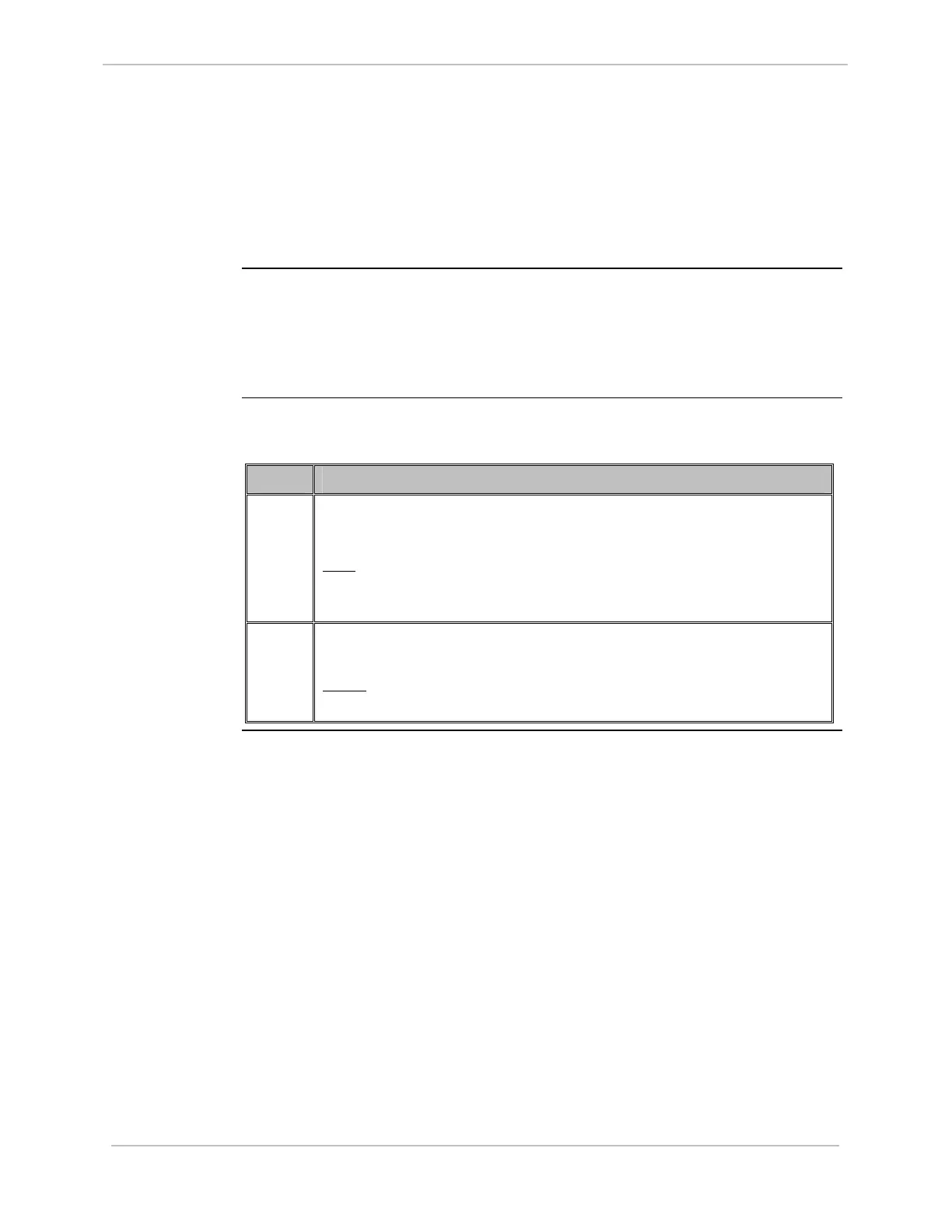
To replace a 5V power supply:
Step Action
1
Remove the 5V Power Supply from the D200 Chassis.
Inspect the right side of the casing.
Note
: In the middle of the right side a slotted dial is visible through
one of the casing apertures. This dial indicates the mains
supply voltage setting: 115V or 220V.
2
Set the voltage by carefully inserting a small screwdriver through the
aperture to turn the dial approximately 45°.
Result
: The mains power supply rating has been set for the Power
Supply.