GE Energy
D20/D200
Installation and Operations Guide
General 994-0078-2.00-7
Full
85
Connections and Configuration, continued
RS-232 Switch
Panel:
Connectors
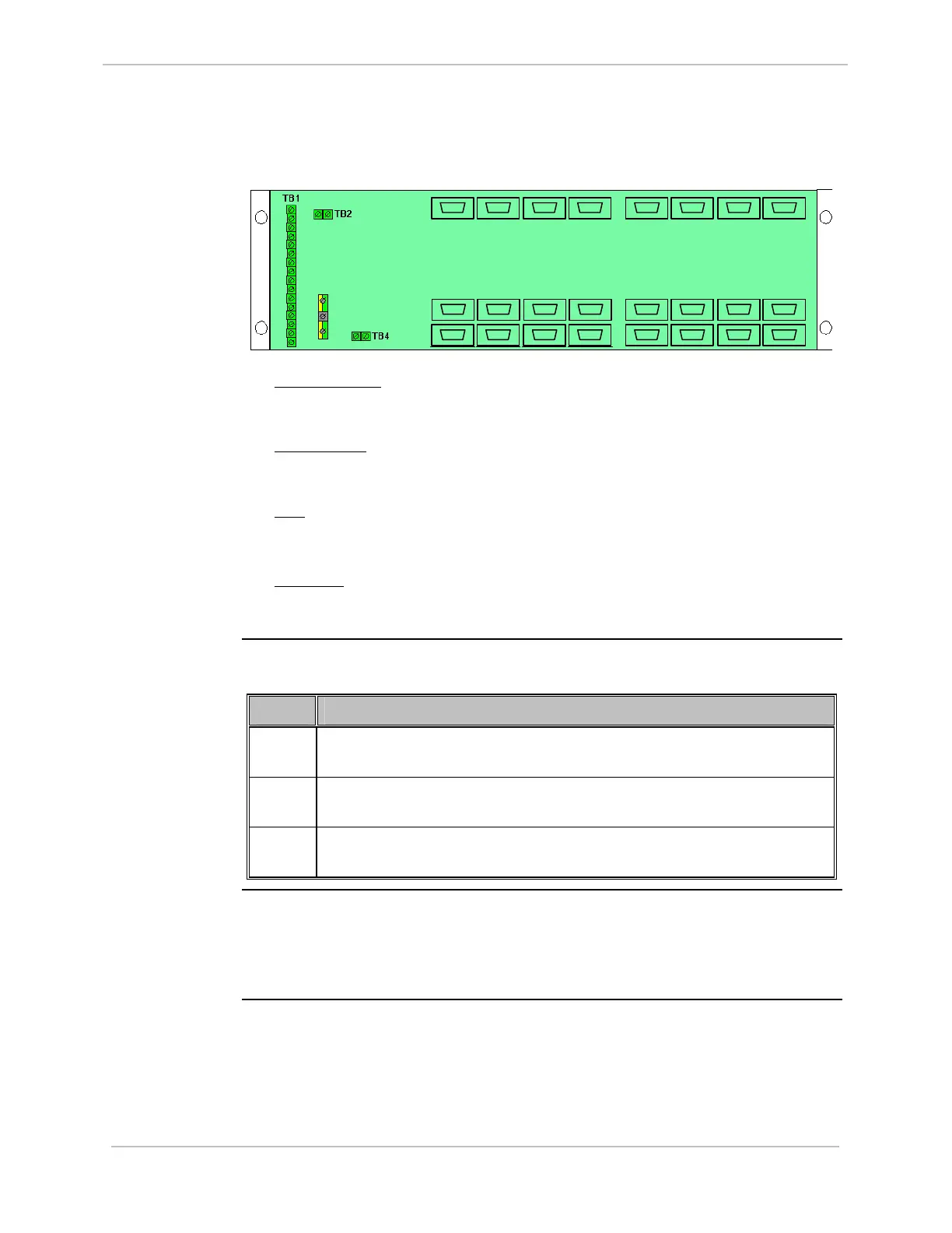
Locate the following connections on the rear of the RS-232 Switch Panel:
• P1 through P16
: The RS-232 Switch Panel can switch up to eight serial
connections from each of the two CCUs - P1 through P8 are connected to CCU
A, and P9 through P16 are connected to CCU B.
• J1 through J8
: Field equipment is connected to these ports. If CCU A is active,
serial connections P1 through P8 are switched to J1 through J8. If CCU B is
active, serial connections P9 through P16 are switched to J1 through J8.
• TB1
: Connector block for connection of the monitor and control cables (referred
to as the Watchdog cables) from each of the CCUs. Refer to Assembly Drawing
977-061-AD
• TB2, TB4
: In systems with more than eight serial connections, used to
interconnect multiple RS-232 Switch Panels, as described in “Redundant Multi-
Node Sy
stems” on page 86.
Procedure:
Installing
Watchdog
Cables
Connect CCUs A and B to the RS-232 Switch Panel using Watchdog cables, as
follows:
Step Action
1
Connect the connectorized end of one of the Watchdog cables to serial
connector 6 on CCU A.
2
Connect the connectorized end of the other Watchdog cable to serial
connector 6 on CCU B.
3
Connect the non-connectorized ends of both Watchdog cables to TB1 on
the RS-232 Switch Panel, as shown in Assembly Drawing 977-0161-AD.
Procedure:
Installing a
Ping Cable
To connect the two CCUs using a Ping cable:
• Connect one end of the Ping cable to serial connector 7 on CCU A, and the other
end to serial connector 7 on CCU B. Refer to Assembly Drawing: 977-0146-AD
for further details.
TB 3
J1
J8
P9
P16
P1
P8
P10
P13
P12P11 P14 P15
P7P6P5P4P3P2
J2 J3 J4 J5
J6
J7