GE Energy
D20/D200
Installation and Operations Guide
General 994-0078-2.00-7
Full
61
Connections and Configuration, continued
D.20 Interface
Modules:
connect for
power using
D.20 Link
Connect power to the D.20 Communications Interface, D.20 Splitter or D.20 DC
Interface modules using D.20 HDLC:
• Use J1 & J7 on the D.20 Communications Interface and D.20 DC Interface
modules. See board diagrams on page 74 and page 78
• Use J1 on the D.20 Splitter
. See board diagram on page 76
Table: J1
pinouts on D.20
Interface
Modules
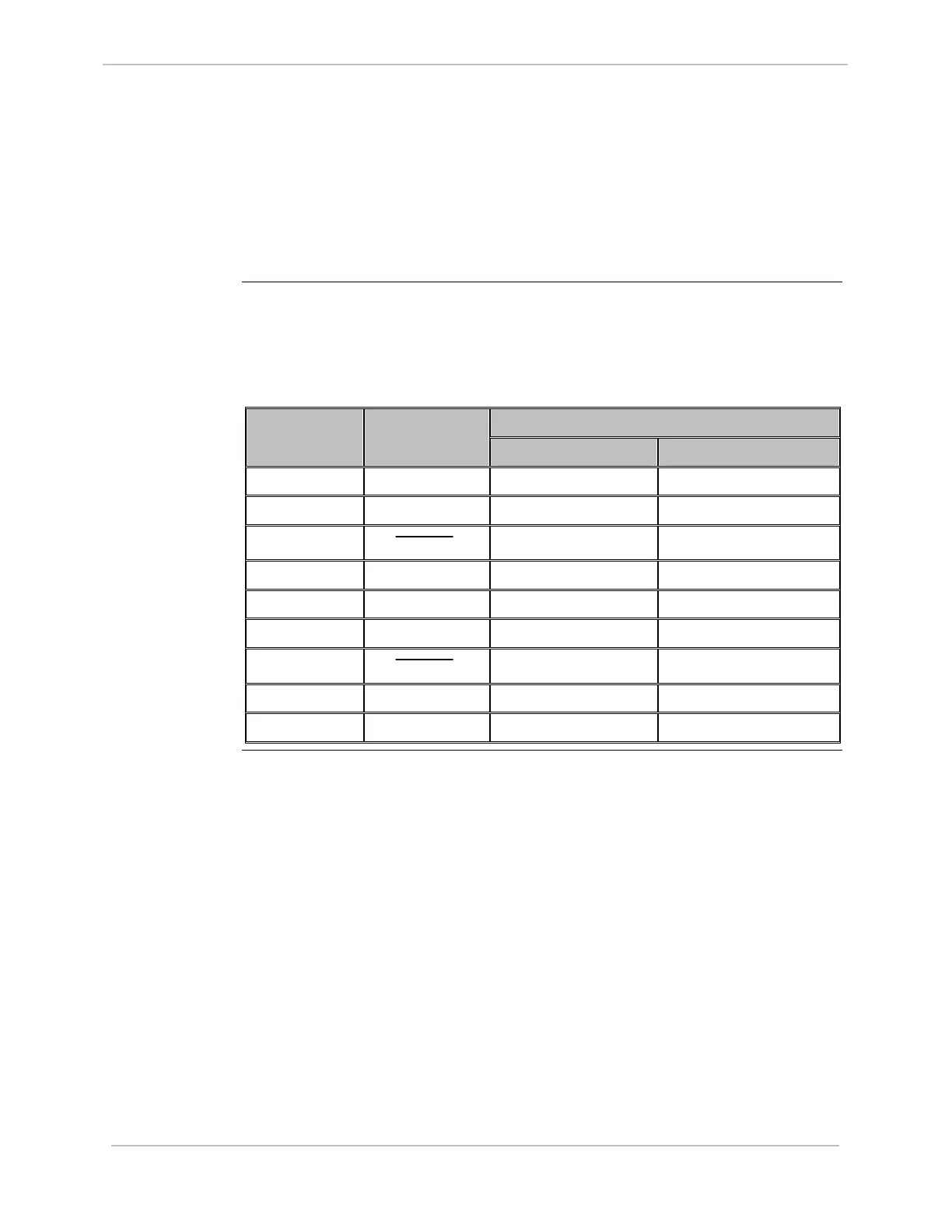
The following table gives DB9 Connector pinouts for J1 and J7 input on the D.20
Interface modules:
Signal Direction Pin Number Function
INPUT OUTPUT
1 GND
2 TX/RX1
√ √
3
TX/RX1
√ √
4 + DC1
√
5 - DC1
√
6 TX/RX2
√ √
7
TX/RX2
√ √
8 + DC2
√
9 - DC2
√