D20/D200
Installation and Operations Guide
GE Energy
994-0078-2.00-7 General
40
Full
Familiarization, continued
D20/D200
Redundancy
Failover
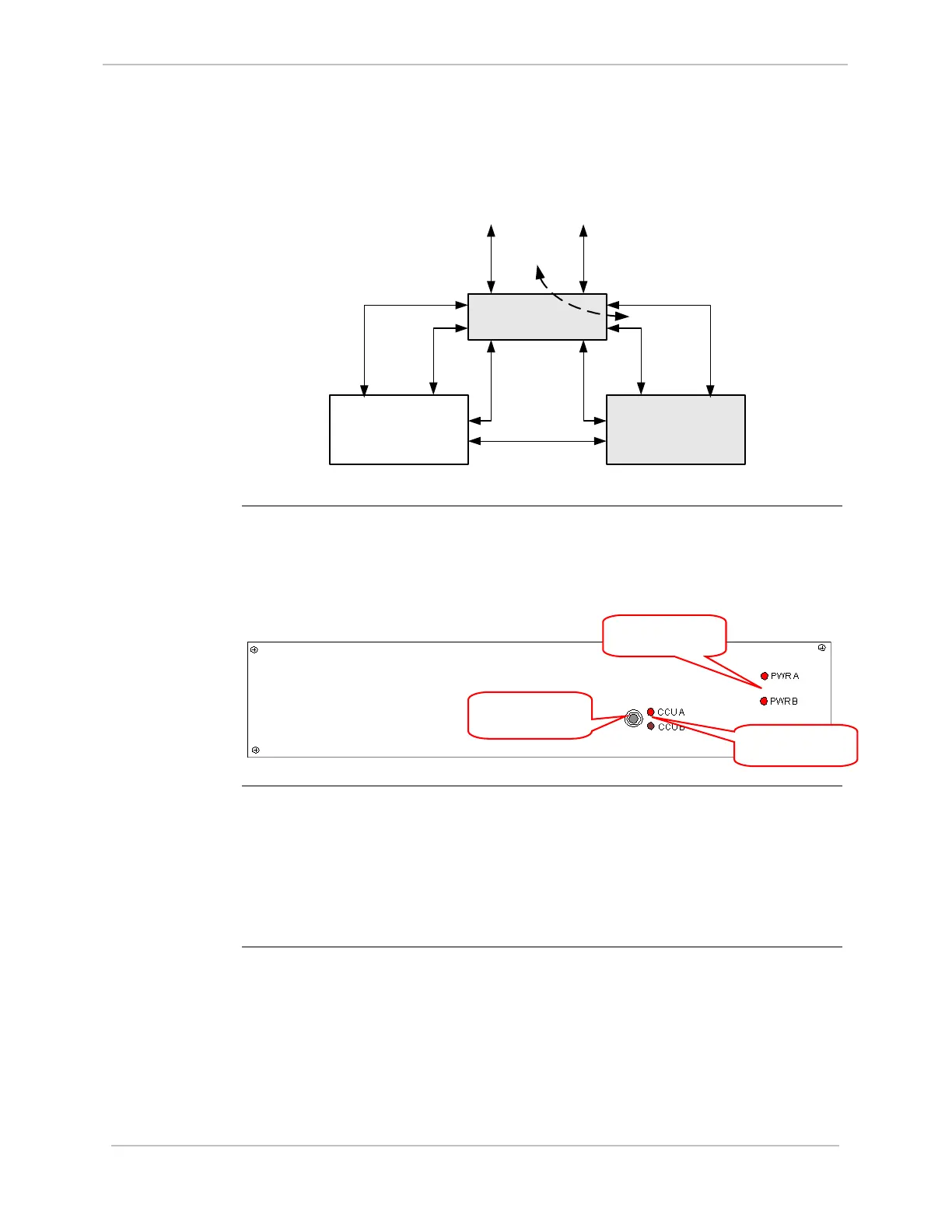
In the example on page 39, if CCU A fails, CCU B becomes active, as shown below:
CCU A
(Failed)
CCU B
(Active)
RS-232 Switch
Monitor and
Control
Inter-CCU
Communications
To Field
Equipment
CCU A Serial
Communications
CCU B Serial
Communications
. . . . . . . . . .
. . . . .
RS-232 Switch Panel
RS-232 Switch
Panel:
Indicators
The RS-232 Switch Panel has two sets of indicator LEDs:
• PWR A/PWR B: When lit, power and communications are received from the
designated CCU. Normally, both LEDs are lit.
• CCU A/CCU B: Normally, one LED is lit, indicating the Active CCU.
RS-232 Switch
Panel:
Active/Standby
Switch
The Active/Standby switch on the front of the RS-232 Switch Panel is used to:
• Restore a previously failed CCU to Active status, once it has been repaired.
• Manually force a CCU to Active status, so routine maintenance can be
performed on the other CCU.
For instructions on operating the Active/Standby switch, refer to “RS-232 Switch
Panel: Active/Standby
Switch Operation” on page 117
CCU Indicator
LEDs
Active/Standby
Switch
Power Indicator
LEDs