GE Energy
D20/D200
Installation and Operations Guide
General 994-0078-2.00-7
Full
81
Connections and Configuration, continued
MIC Jumper
Options
Each of the two channels on the MIC includes a set of jumpers to enable or disable
various operational modes.
Note:
The three module types have different jumper configurations, so be sure to
use the correct table for your module.
10BASE-T
MIC Jumper
Settings
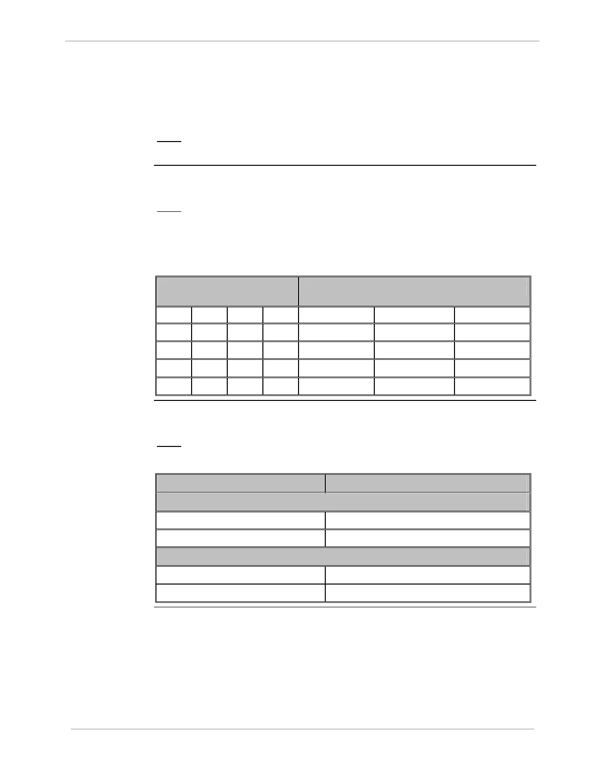
The following table specifies the jumper settings to enable or disable the various
operational modes of each of the two channels of the 10BASE-T MIC:
Note:
The default jumper setting is: JP1 and JP2 jumpers 7-8 In, all other
jumpers Out, disabling the SQE Test mode.
This is the mode usually used with 10BASE-T Ethernet hub networks.
Jumper JP1 (Ch 1)
and JP2 (Ch 2)
Mode of Operation
1-2 3-4 5-6 7-8 SQE Test Link Test Jabber
Out Out Out In Disabled Enabled Enabled
Out Out In Out Disabled Disabled Disabled
Out In Out Out Enabled Disabled Enabled
In Out Out Out Enabled Enabled Enabled
10BASE2 MIC
Jumper
Settings
Each of the two channels of the 10BASE2 MIC includes a jumper to enable and
disable SQE Test.
Note:
The default setting is SQE Test Enabled for both channels.
Jumper Position Mode of Operation
Channel 1 Mode Jumpers
JP1 – Out SQE Test Enabled
JP1 – In SQE Test Disabled
Channel 2 Mode Jumpers
JP2 – Out SQE Test Enabled
JP2 – In SQE Test Disabled