GE Energy
D20/D200
Installation and Operations Guide
General 994-0078-2.00-7
Full
49
Connections and Configuration, continued
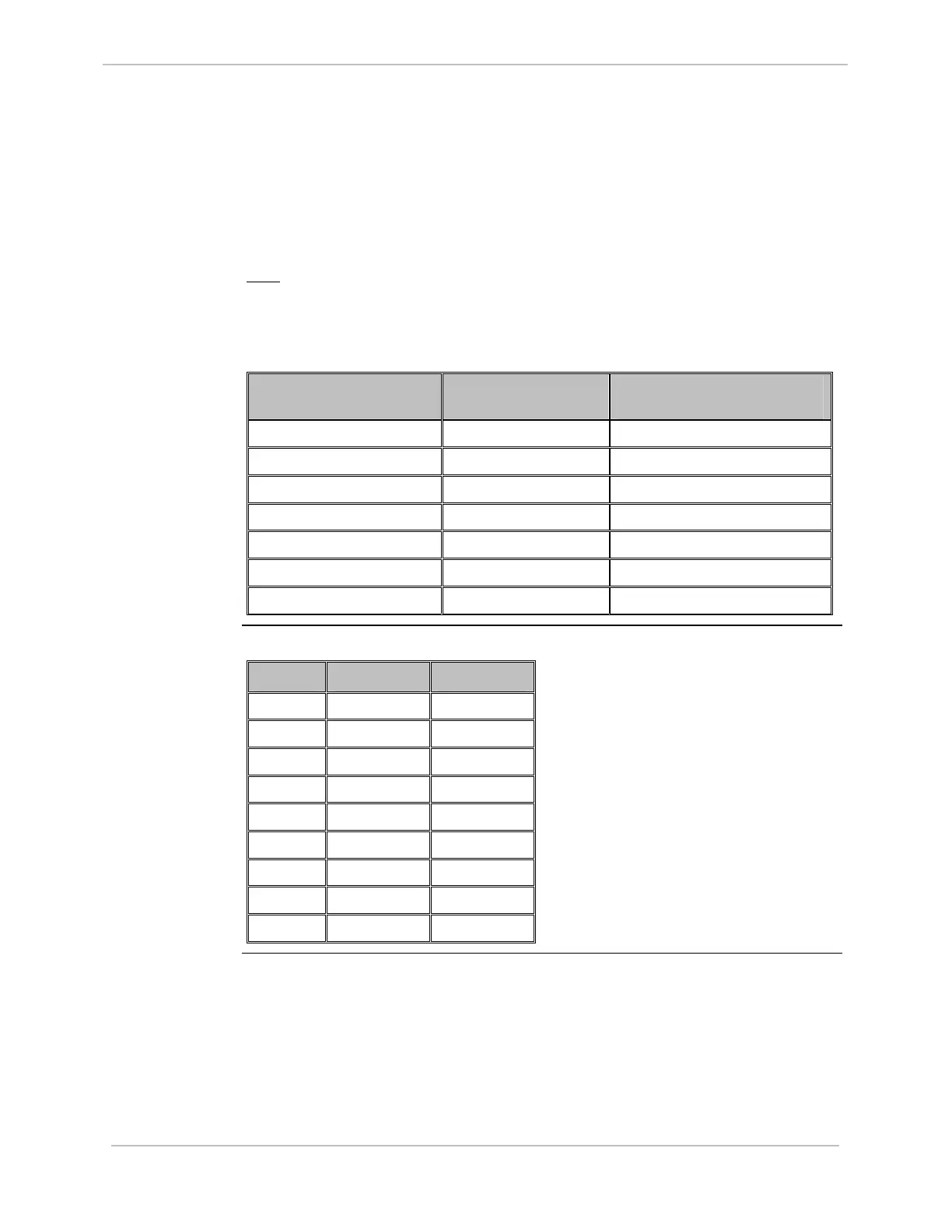
D20ME II Jumpering, continued
JP11
RS-232/RS-485
Operation
A JP11 jum
per is always installed in conjunction with a serial communications port
channel. The jumper's position depends on whether the channel has been mode
selected as either RS-232 or RS-485 (see SW2).
Note
: In order for RS485 (RS422) to operate, the RTS ON/OFF setting must be
enabled and both DCD and CTS must be disabled in Config Pro specific to
the protocol being used for that serial port. RTS must be toggled ON for
RS485 transmissions and may be set continuously ON for RS422 data
transmissions.
Serial Comm Port JP11 (pins) RS-232
JP11 (pins) RS-485(RS-422)
Enabled
1 1-2 2-3
2 4-5 5-6
3 7-8 8-9
4 10-11 11-12
5 13-14 14-15
6 16-17 17-18
7 19-20 20-21
Table: Serial
Port Pinouts
Pinouts for serial ports for both RS-232 and RS-485 configurations.
DB-9 Pin RS-232 RS-485
1 CD N/C
2 RX RX-
3 TX TX-
4 N/C N/C
5 GND Com GND
6 N/C N/C
7 RTS TX+
8 CTS RX+
9 EARTH GND EARTH GND