GE Energy
D20/D200
Installation and Operations Guide
General 994-0078-2.00-7
Full
87
Connections and Configuration, continued
Redundant
Multi-Node
Systems:
Example
If your D20/D200 multi-node system supports more than eight serial communication
links, you need a second RS-232 Switch Panel to switch the additional serial links.
This is illustrated in the following example:
Consider the case where you connect seven serial links to the first slave node, and
four serial links to the second slave node, for a total of eleven serial links. In this
case, you need two RS-232 Switch Panels. One RS-232 Switch Panel is designated
the Master RS-232 Switch Panel and the second the Slave RS-232 Switch Panel.
Cable the Master RS-232 Switch Panel as follows:
• Connect the Master RS-232 Switch Panel to both CCUs, using Watchdog cables.
• Connect the seven serial links from the first slave node Termination Panel to the
Master RS-232 Switch Panel.
• Connect TB4 pins 1 and 2 (SET and RESET respectively) on the Master RS-232
Switch Panel to TB2 pins 1 and 2 on the Slave RS-232 Switch Panel.
Cable the Slave RS-232 Switch Panel as follows:
• Connect the four serial links from the second slave node Termination Panel to
the Slave RS-232 Switch Panel.
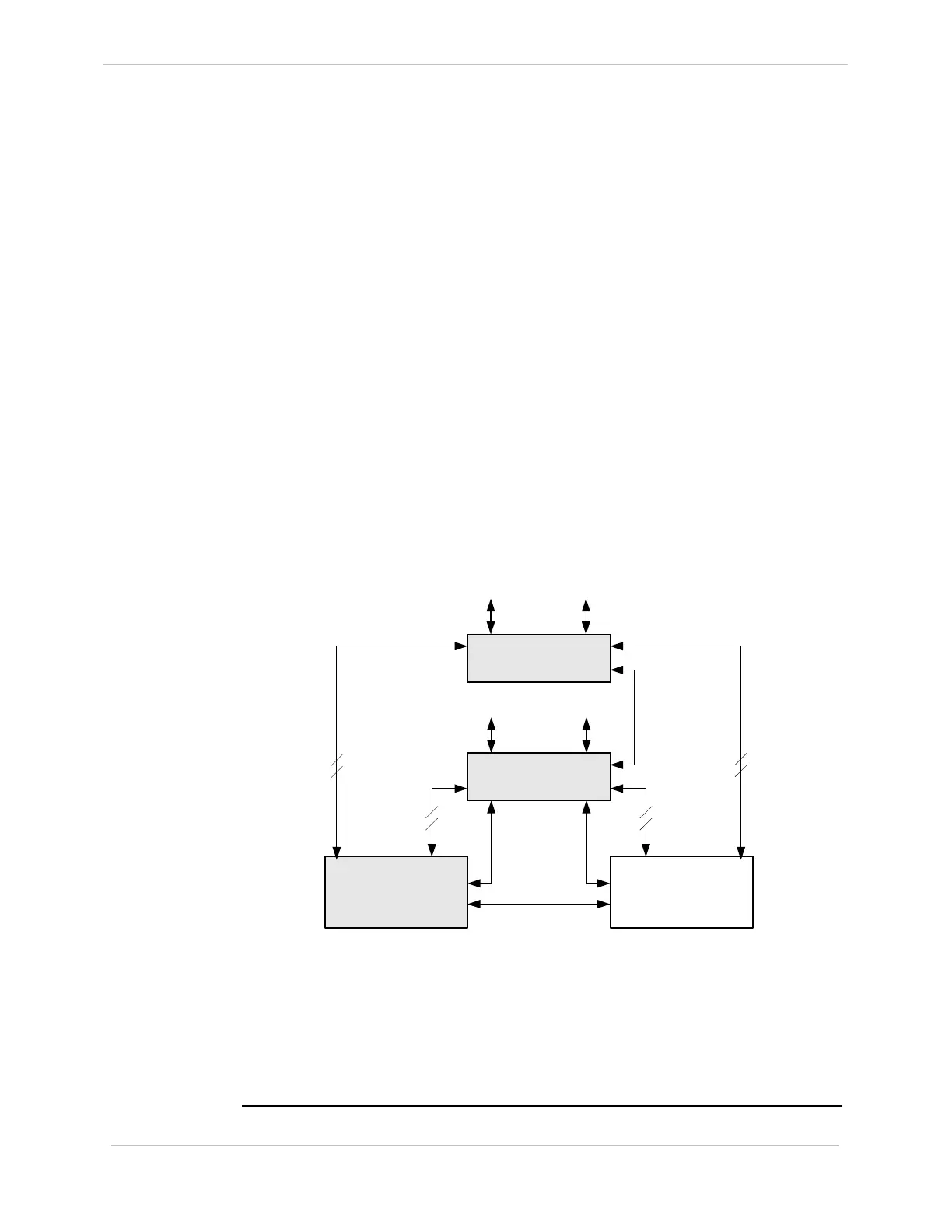
This example configuration is illustrated below:
Master RS-232 Switch
Panel
CCU A
(Active)
CCU B
(Standby)
Watchdog
Cables
Ping or HDLC Cable
To Field
Equipment
Slave RS-232 Switch
Panel
To Field
Equipment
TB4
TB2
7 serial links
from first
slave node
7 serial links
from first
slave node
4 serial links
from second
slave node
4 serial links
from second
slave node
Note: Since RS-232 Switch Panels support eight serial connections, for efficiency,
you could also cable one serial link from the second D20 slave node to the
Master RS-232 Switch Node, and the remaining three links to the Slave RS-
232 Switch Panel.
Note: A maximum of eight RS-232 Switch Panels can be cascaded. The total
cable length between the master and slaves can not exceed 3 meters.