GE Energy
D20/D200
Installation and Operations Guide
General 994-0078-2.00-7
Full
75
Connections and Configuration, continued
D.20 Comm
Interface:
Settings
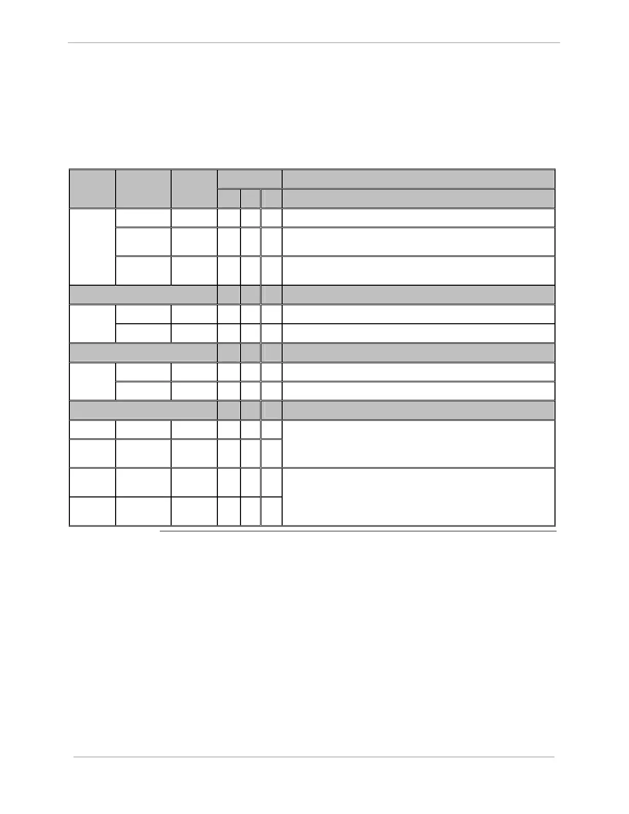
The following table gives jumper settings for Z1 to Z14.
Option 1 Jumper Definition – External Power Jumper
Number
Jumper
Position
Jumper
Setting
1A 1B 1C
2 – 3 IN
√
D.20 Link Power Supplies J8 & Comm. I/F
3 – 4 IN
√
External Power on TB1 supplies J8 only and D.20 Link power supplies
Comm. I/F
Z1 to Z4
1 – 4 & 2 –
3
IN
√
External Power on TB1 supplies D.20 Link, J8 and Comm. I/F
2A 2B
Jumper Definition – D.20 Channel Used
1 – 2 IN
√
D.20 Channel 1 Used Z5 to Z6
2 – 3 IN
√
D.20 Channel 2 Used
3A 3B
Jumper Definition – Repeater Channel (N/A)
1 – 2 IN
√
RS-485 Interface Connected to D.20 Channel 1 Z7 to Z8
2 – 3 IN
√
RS-485 Interface Connected to D.20 Channel 2
4A 4B
Jumper Definition – S/W Base Compatibility
Z9 to Z12 1 – 2 ALL IN
√
Z13 &
Z14
1 – 2 IN
√
Base 3.11, Pre-Win or Older
Z9 to Z12 1 – 2 ALL
OUT
√
Z13 &
Z14
2 – 3 IN
√
ALL OTHER BASES