D20/D200
Installation and Operations Guide
GE Energy
994-0078-2.00-7 General
18
Full
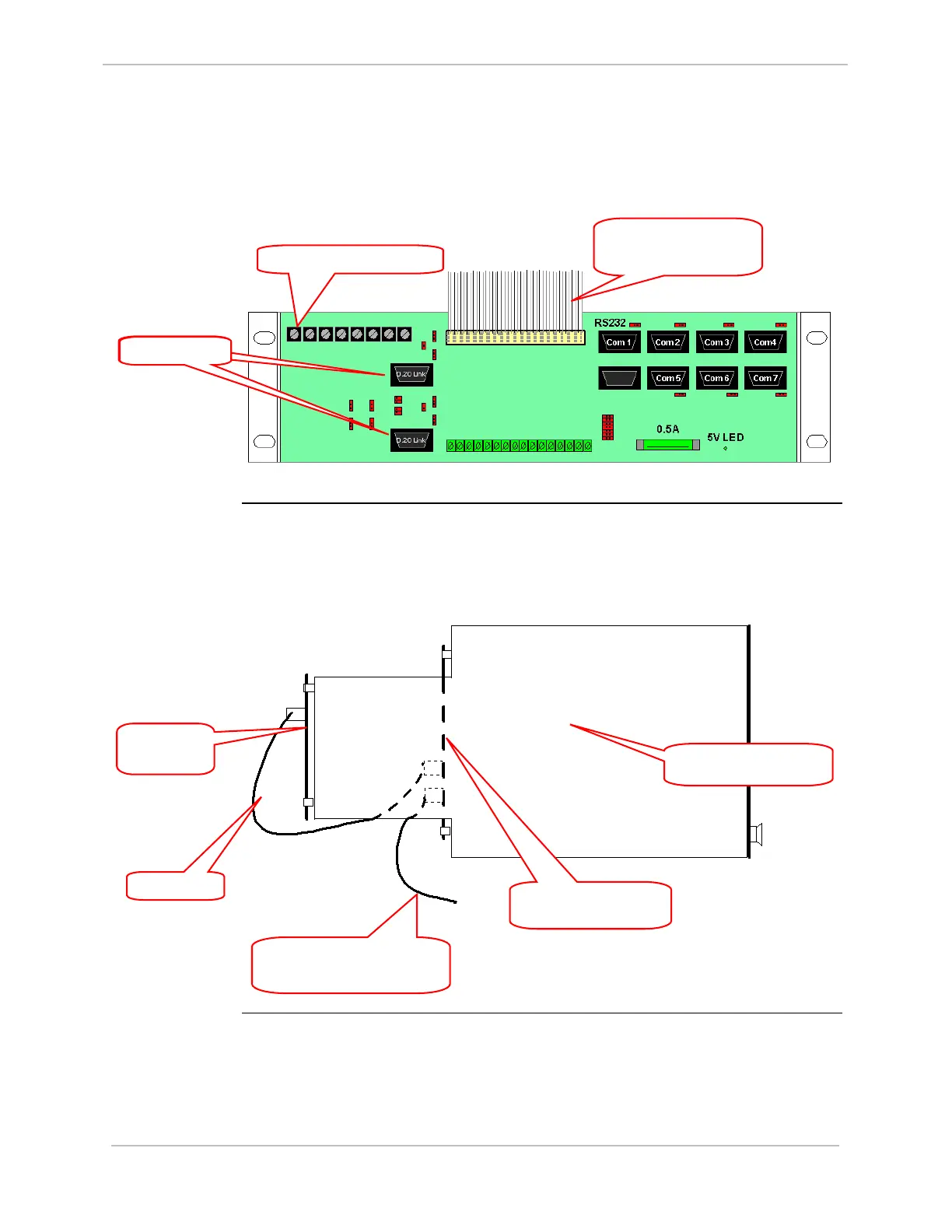
Familiarization, continued
WESTERM
D20M+
Termination
Panel:
Method 1
The WESTERM D20M+ can be
mounted in two ways:
1. With the standard chassis it is mounted separately into the 19” standard rack on a
2U mounting plate:
WESTERM
D20M+
Termination
Panel:
Method 2
2. With the MX chassis it is mounted behind the WESTERM D20VME bus
backplane. This leaves more room on the rack for multi-node
installations:
Side of D20 MX
Chassis
Ribbon Cable
FRONT
REAR
WESTERM
D20M+
WESTERM D20VME
bus backplane
Ribbon cable connector
from the WESTERM
D20VME bus back
lane
Power Termination Block
Ribbon Cable connecting to
additional rack-mounted
WESTERM D20M+
D.20 Link Ports
D.20 Link Ports