D20/D200
Installation and Operations Guide
GE Energy
994-0078-2.00-7 General
74
Full
Connections and Configuration, continued
D.20 Interface
Modules
Jumper location and configuration settings for the D.20 Communication Interface
and D.20 DC Interface are given below. You can also refer to the Module Layouts
for these boards:
• D.20 Communications Interface and D.20 RS-485 Adaptor
− see 520-0117-ML
• D.20 Splitter
− see 520-0118-ML
• D.20 DC Interface
− see 520-0154-ML
D.20 Comm
Interface:
Jumpers
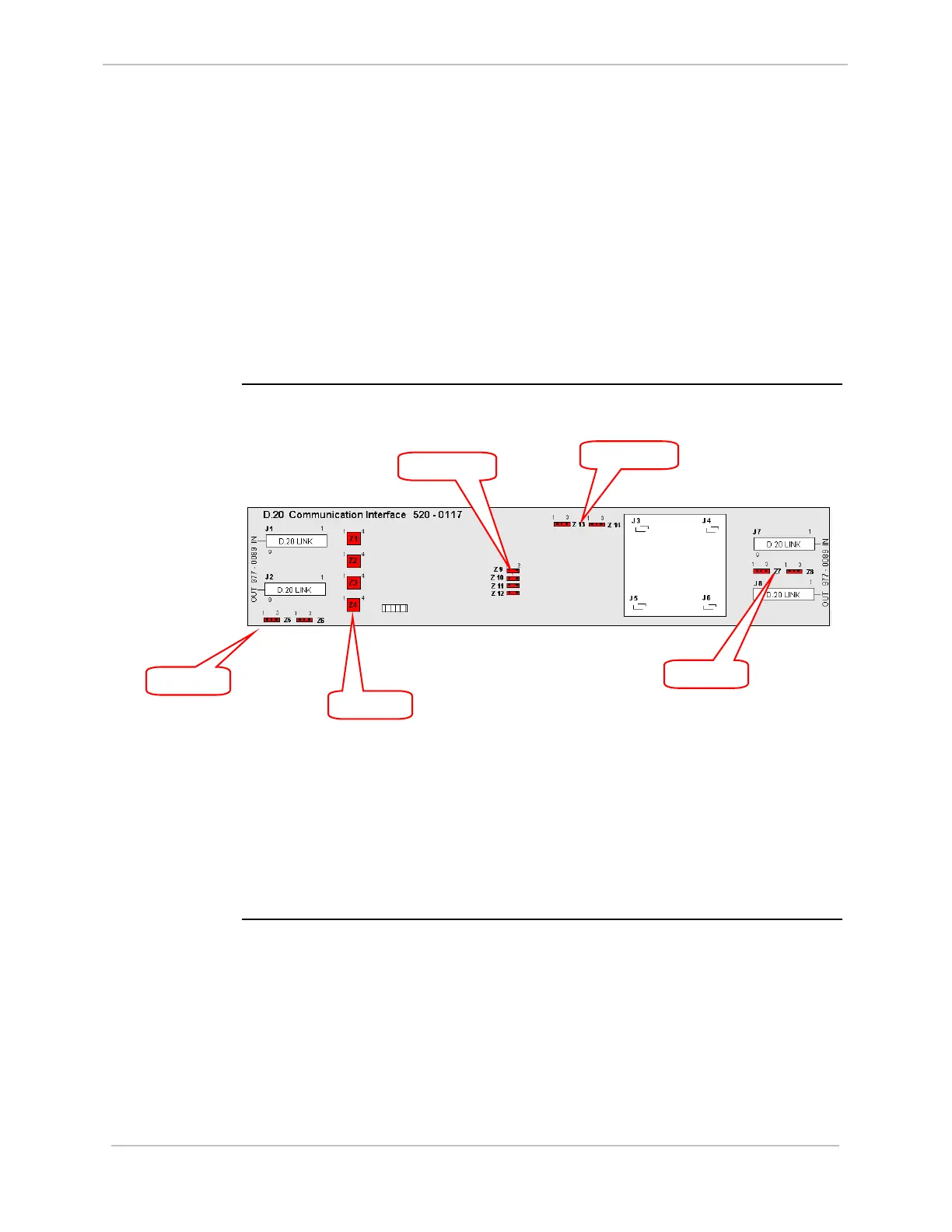
Jumper locations on the D.20 Communications Interface:
Use jumpers:
• Z1 to Z4 for external power setting
• Z5 and Z6 for D.20 channel used
• Z7 and Z8 for Repeater channel used
• Z9 to Z14 for SW base compatibility setting
See table below, next page.
Z5 & Z6
Z1 to Z4
Z7 & Z8
Z9 to Z12
Z13 & Z14