GE Energy
D20/D200
Installation and Operations Guide
General 994-0078-2.00-7
Full
73
Connections and Configuration, continued
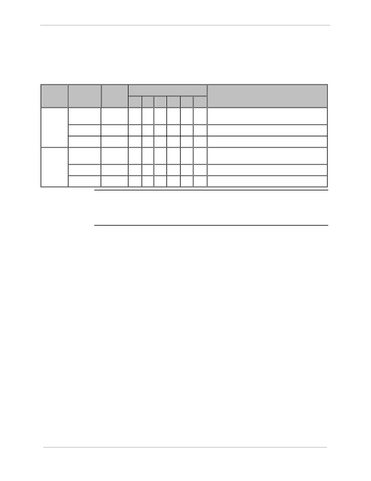
WESTERM D20C: Settings (continued)
Option 3 Jumper
Number
Jumper
Position
Jumper
Setting
3A 3B 3C 3D 3E 3F
Jumper Definition – Control O/P
Configuration
1 – 2 & 3 –
4
IN
√
√
T/C Configuration (T/C 5 & 6)
1 – 2 IN
√
√ √
R/L Configuration (R/L 2)
Z11 &
Z15
2 – 3 IN
√
From C Control Outputs 5 & 6
1 – 2 & 3 –
4
IN
√
T/C Configuration (T/C 7 & 8)
1 – 2 IN
√ √ √ √
R/L Configuration (R/L 1)
Z12 &
Z16
2 – 3 IN
√
Form C Control Outputs 7 & 8
WESTERM
D20AC
There is only the Z1 jumper on the WESTERM D20AC. It is located in a similar
position to Z1 on the A, S, K, and C boards.