GE Energy
D20/D200
Installation and Operations Guide
General 994-0078-2.00-7
Full
55
Connections and Configuration, continued
Peripherals:
connect for
power using
D.20 Link
Connect power to A, S, K, C, and AC peripheral boards using the D.20 HDLC Link
using a daisy-chain series of connections from peripheral to peripheral.
Procedure
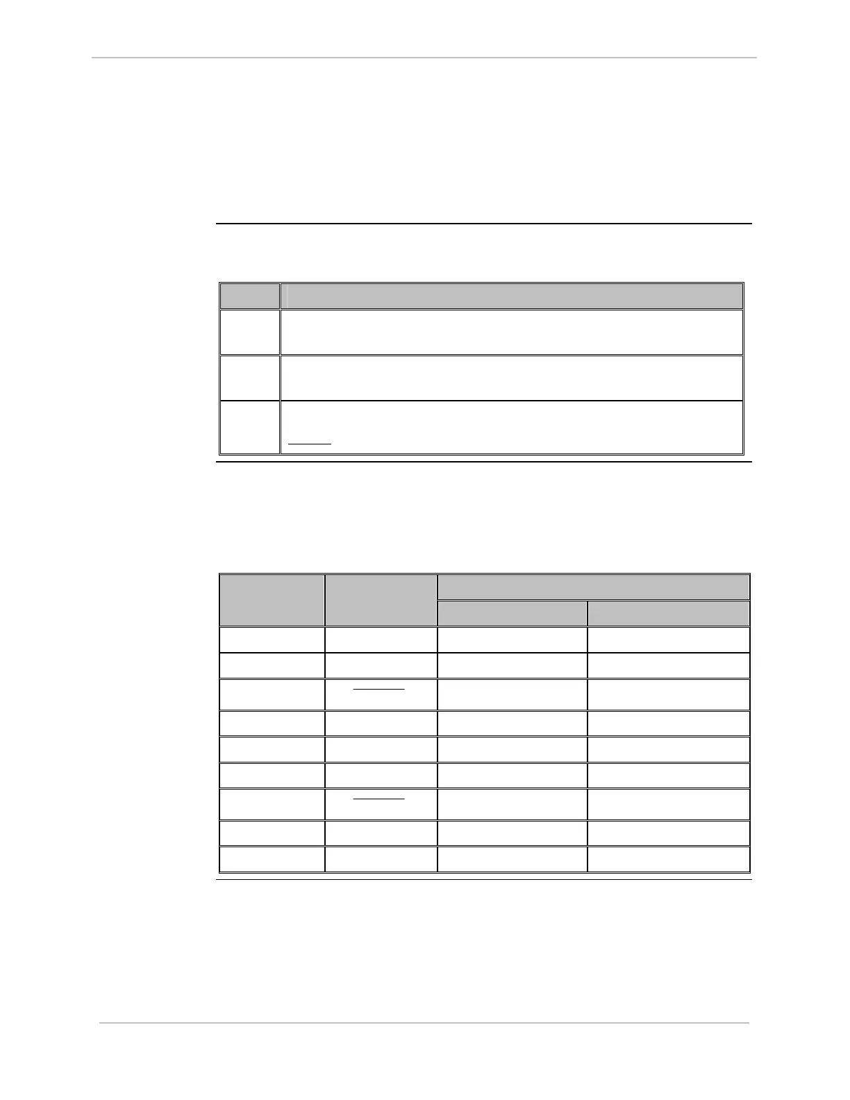
Connect peripherals using the D.20 Link:
Step Action
1
Connect the D.20 link DB9 connector to the JI input on WESTERM
peripheral board number one.
2
Connect the D.20 link DB9 connector out from the J2 connector and into
the J1 connector on WESTERM peripheral board number two.
3
Repeat steps 1 and 2 for each WESTERM peripheral board in series.
Result:
The peripherals are connected for power using the D.20 Link.
Table: J1
pinouts on
WESTERM
Peripherals
The following table gives DB9 Connector pinouts for J1 input on the WESTERM
boards:
Signal Direction Pin Number Function
INPUT OUTPUT
1 GND
2 TX/RX1
√ √
3
TX/RX1
√ √
4 + DC1
√
5 - DC1
√
6 TX/RX2
√ √
7
TX/RX2
√ √
8 + DC2
√
9 - DC2
√