GE Energy
D20/D200
Installation and Operations Guide
General 994-0078-2.00-7
Full
19
Familiarization, continued
D200
The D200 is available in a vertical-slot chassis. A D200 chassis typically contains:
• Chassis with six feet of 12AWG Green/Yellow ground wire
• Main processor board
• Power supply
• WESMAINT maintenance port cable
• Software loaded into main processor, see “D20ME/ME II Factory Fitted
Software” on page 25.
• D20EME Ethernet/Me
mory expansion board, see “D20EME”, page 35
• D20M++ Termination pan
el
Modems are options for the Main Chassis kit.
Table
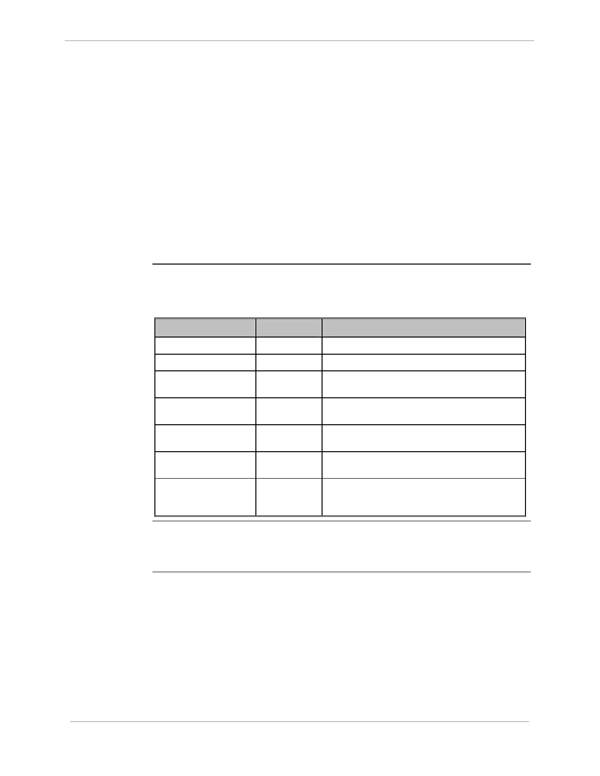
The D200 has a 6U 9 vertical slot chassis for 19” rack mounting. There are seven
types of chassis:
Chassis Type Part # Description
D200 VME 6U 240 VAC 500-0306 Chassis for 120/240 Volts AC Power Supply in
D200 VME 6U 48VDC 500-0307 Chassis for 48 Volts DC Power Supply in
D200 6U VME 48 VDC
WO Term Board
500-0308 Chassis for 48 Volts DC Power Supply in without
termination panel
D200 VME 6U Dual
48VDC
500-0310 Chassis for dual 48 Volts DC Power Supplies in
D200 VME, DUAL
48VDC, DUAL TERM
500-0311 Chassis for dual 48 Volts DC Power Supplies in and
dual termination boards
D200 VME, SINGLE
48VDC with 24VDC ISO
500-0312 Chassis for single 48 Volts DC Power Supply in and
24 Volts DC out to system components
D200 VME, Dual
48VDC, Dual Term, with
4 D.20 Links
500-0317 Chassis for dual 48 Volts DC Power Supplies in, dual
termination panel and 4 D.20 Links
Chassis
Compatibility
See “Appendix A: Product Combinations”, for the possible matching of main
processor board, Ethernet and m
emory expansion card combinations with chassis
types.