D20/D200
Installation and Operations Guide
GE Energy
994-0078-2.00-7 General
80
Full
Connections and Configuration, continued
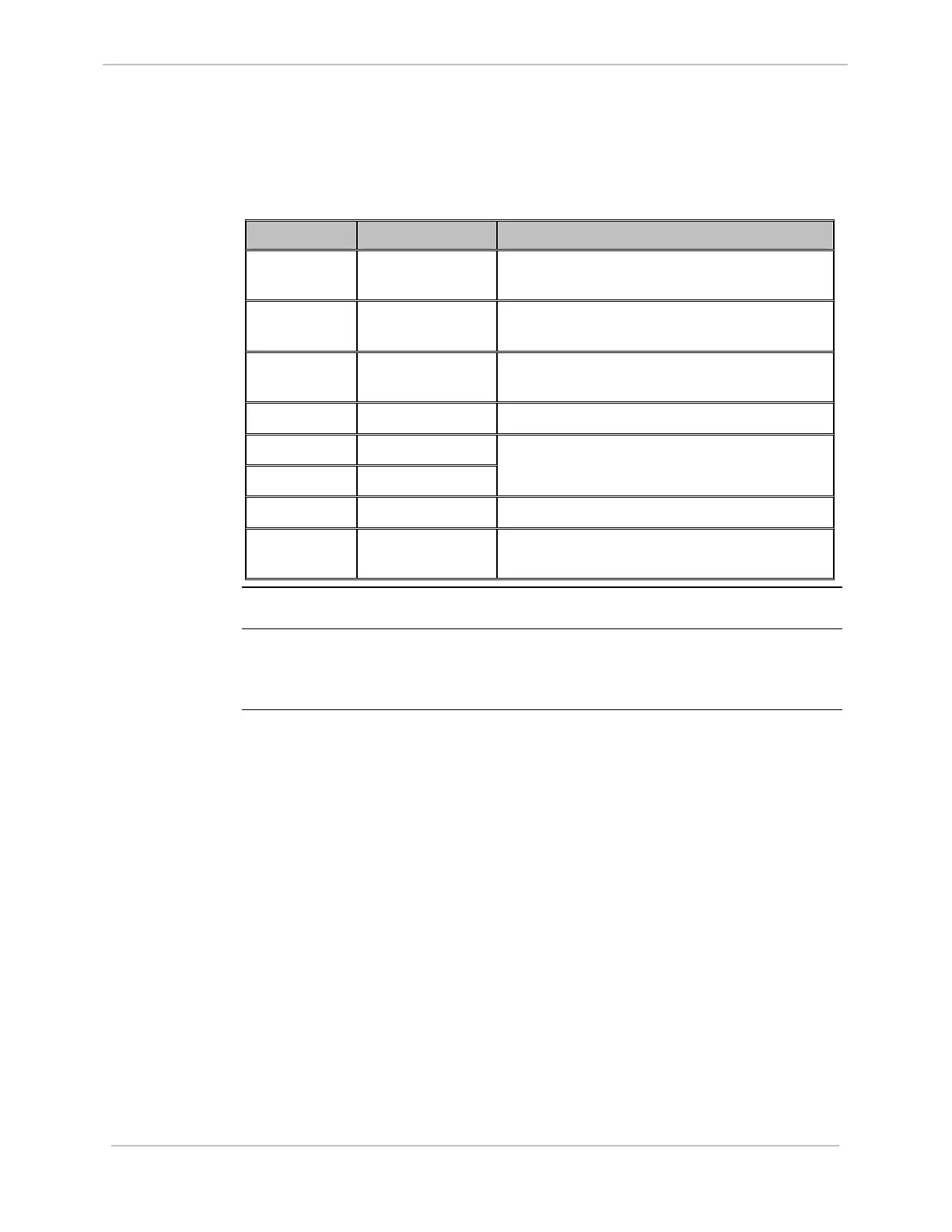
Table: Main
Components
This table identifies some of the D20EME main board’s important components.
Component Name Function
JP5 Battery
disconnect jumper
Removable jumper when storing board for
extended periods.
BT1, BT2 Lithium batteries Maintain NVRAM in the event of a power
failure.
J1, J2 Connectors To connect the optional memory expansion
daughter board.
P4 Connector Power and communication link to MIC.
D11-A BATT 1 LED
D11-B BATT 2 LED
Lights when battery voltage drops below 3
Volts. Replace battery immediately.
D12-A POWER LED +5 Volts power is available.
D12-B ACCESS LED Indicates D20EME is being accessed from
VME bus.
D20EME LEDs
For LED operation See “D20EME LEDs”, page 116.
Memory
Expansion
Card
The Memory Expansion card has no user-configurable options.