D20/D200
Installation and Operations Guide
GE Energy
994-0078-2.00-7 General
82
Full
Connections and Configuration, continued
10BASE-FL
MIC Jumper
Settings
Each of the two channels of the 10BASE-FL MIC includes a set of three jumpers to
enable and disable various operational modes.
Note:
The default jumpering is all jumpers out, enabling SQE test and Jabber,
disabling loop back.
Jumper Mode of Operation
Channel 1 Mode Jumpers – JP1
1-2 3-4 5-6 SQE Test Jabber Loop back
Out Out Enabled Enabled
In Out Disabled Enabled
Out In Disabled Disabled
In Enabled
Out Disabled
Channel 2 Mode Jumpers – JP2
1-2 3-4 5-6 SQE Test Jabber Loop back
Out Out Enabled Enabled
In Out Disabled Enabled
Out In Disabled Disabled
In Enabled
Out Disabled
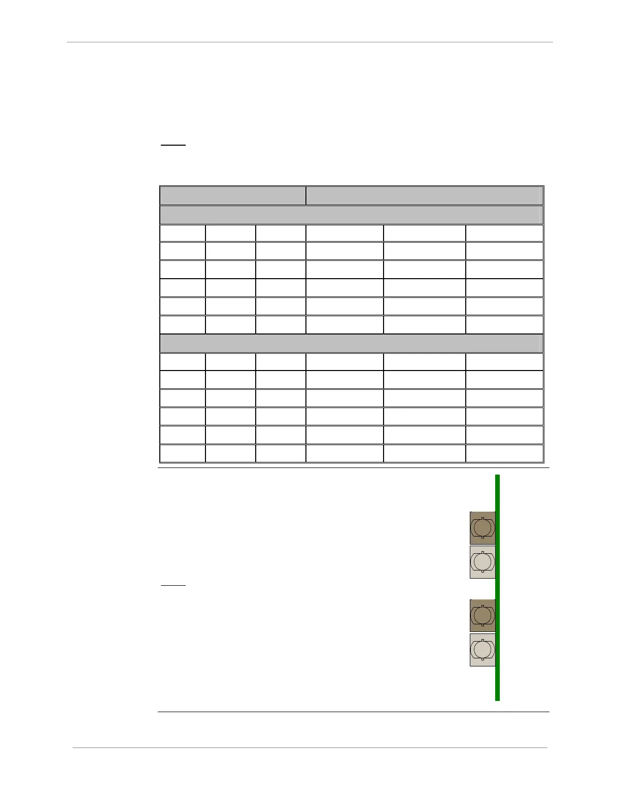
10BASE-FL
Fiber Cable
Connectors
The 10BASE-FL module has four ST-Type
bayonet fiber-optic cable connectors on the
rear edge of the card.
The positions of the input and output
connectors for each channel are shown in the
diagram to the right.
Note:
Labels can be seen on the PCB
stencil, beside each of the
connectors.
LAN A
Receive
LAN B
Receive
LAN A
Transmit
LAN B
Transmit
Rear View of
10BASE-FL MIC