GE Energy
D20/D200
Installation and Operations Guide
General 994-0078-2.00-7
Full
53
Connections and Configuration, continued
Termination
Panels: Jumper
Settings
There are three WESTERM Termination Panels. For jumper configuration settings
for each of these boards see the Module Layout drawings:
• WESTERM D20M+ SS for non-VME see 517-0224-ML
• WESTERM D20M+ for VME see 517-0225-ML
• WESTERM D20M++ for VME see 517-0245-ML
Termination
Panels: Power
Supply
Power connections to the WESTERM Termination Panels are made on connector
blocks:
• TB1 on the WESTERM D20M+ SS and WESTERM D20M+
• TB2 on the WESTERM D20M++
WESTERM
D20M+SS:
Power Supply
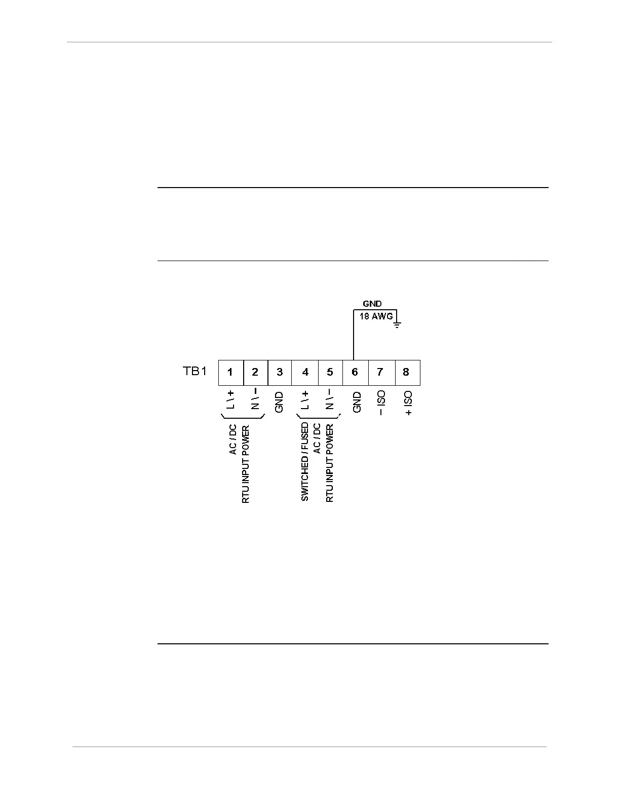
Power Supply connections on WESTERM D20M+ SS and WESTERM D20M+:
• 1 & 2 are used for input power connections based on the WESDAC D20 Power
Supply
• 4 & 5 can be used as a switched auxiliary power supply source
• 7 & 8 can be used externally for status wetting, contact wetting and/or
miscellaneous power connections, if applicable.