D20/D200
Installation and Operations Guide
GE Energy
994-0078-2.00-7 General
66
Full
Connections and Configuration, continued
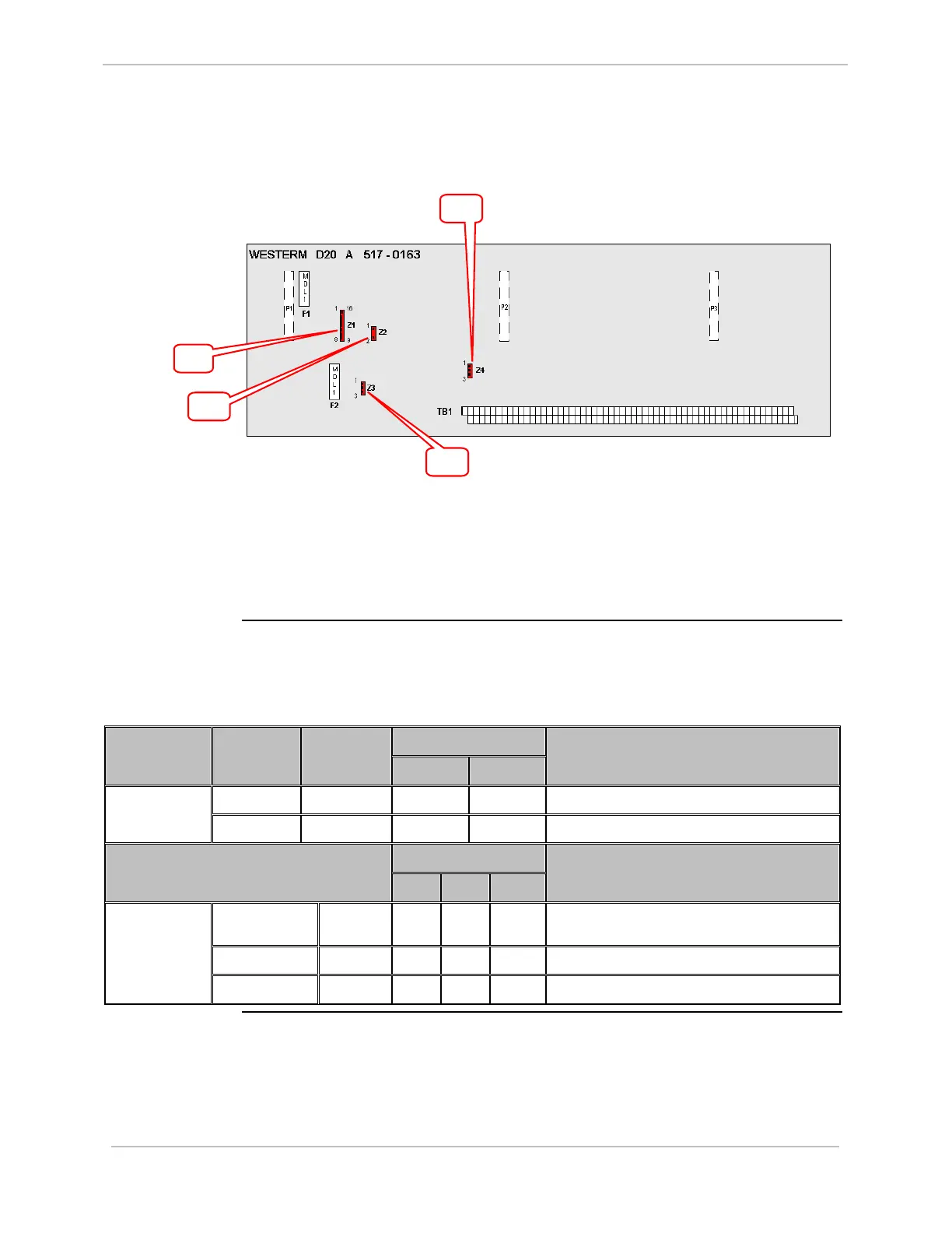
WESTERM
D20A: Jumpers
Jumper locations on the WESTERM D20A:
To set Module address jumpering on Z1, see “WESTERM Addressing”, page 65.
Use ju
mpers:
• Z2 to enable/disable low loop supply voltage sensing
• Z3 and Z4 to set Analog loop supply.
WESTERM
D20A: Jumper
Settings
The following table gives jumper settings for Z2, Z3 and Z4.
Option 1 Jumper
Number
Jumper
Position
Jumper
Setting
1A 1B
Jumper Definition – Low Loop Supply
1 – 2 IN
√
Enable bypass for low loop supply sensing Z2
1 – 2 OUT
√
Disable bypass for low loop supply sensing
Option 2
2A 2B 2C
Jumper Definition – Analog Loop Supply
1 – 2 IN
√
Internal Analog loop supply provided by DC1 or
DC2
2 – 3 IN
√
External Analog loop supply on TB1-1 & 3
Z3 & Z4
1 – 2 & 2 – 3 OUT
√
Not required
Z1
Z2
Z3
Z4