D20/D200
Installation and Operations Guide
GE Energy
994-0078-2.00-7 General
84
Full
Connections and Configuration, continued
Required
Components
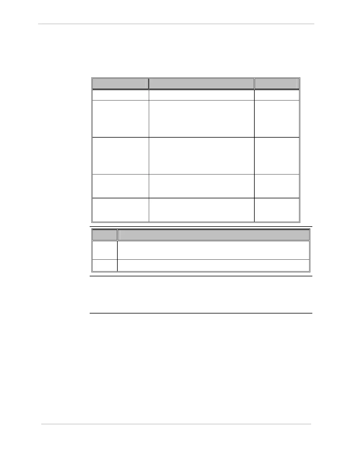
To implement a redundant D20/D200 system, you need the following components
and cables:
Component Function Part Number
RS-232 Switch Panel Communication switch. 517-0247
Watchdog Cable
Assembly (D20)
For VME and non-VME D20 systems,
two cable assemblies are required, one
connecting CCU A to the RS-232 Switch
Panel, the other connecting CCU B to the
RS-232 Switch Panel.
977-0160
Watchdog Cable
Assembly (D200)
For D200 systems, two cable assemblies
are required, one connecting CCU A to the
RS-232 Switch Panel, the other
connecting CCU B to the RS-232 Switch
Panel.
977-0161
Ping Cable Assembly Connects CCU A to CCU B, when a ping
connection is used for communication
between the two CCUs.
977-0146
HDLC Cable
Assembly
Connects CCU A to CCU B, when a D.20
HDLC connection is used for
communication between the two CCUs.
977-0089
Redundant
System:
Mounting the
Hardware
Step Action
1
Mount the second CCU and connect power and ground, as shown in the
module layout drawing.
2
Mount the RS-232 Switch Panel.
Redundant
System:
Software
Configuration
Configure your CCUs for redundancy, using Config Pro. Refer to the Config Pro
online help for instructions.