D20/D200
Installation and Operations Guide
GE Energy
994-0078-2.00-7 General
68
Full
Connections and Configuration, continued
WESTERM
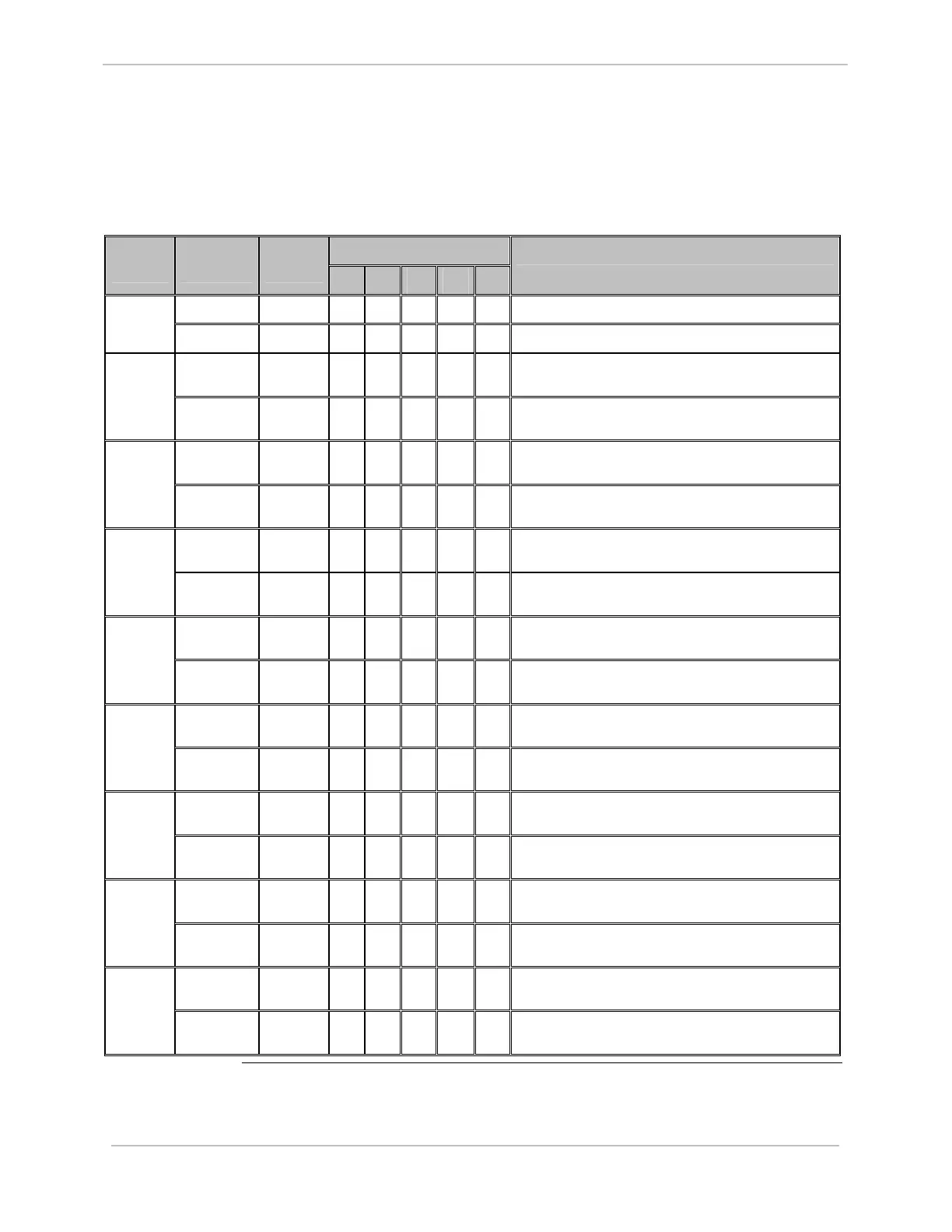
D20S: Settings
The following table gives jumper settings for Z2 to Z11.
Option Jumper
Number
Jumper
Position
Jumper
Setting
1A 1B 1C 1D 1E
Jumper Definition – Status
1 – 2 IN
√
√
D20 Peripheral DC Supply Voltage Z2 & Z3
2 – 3 IN
√
√
External DC Supply Voltage on TB1-65 and 131
1 – 2 & 3 –
4
IN
√ √
Contact Wetting Configuration (DI 1 – 8) Z4
2 – 3 IN
√ √
Group Common Configuration with Voltage Input
(DI 1 – 8)
1 – 2 & 3 –
4
IN
√ √
Contact Wetting Configuration (DI 9 – 16) Z5
2 – 3 IN
√ √
Group Common Configuration with Voltage Input
(DI 9 – 16)
1 – 2 & 3 –
4
IN
√ √
Contact Wetting Configuration (DI 25 – 32) Z6
2 – 3 IN
√ √
Group Common Configuration with Voltage Input
(DI 25 – 32)
1 – 2 & 3 –
4
IN
√ √
Contact Wetting Configuration (DI 17 – 24) Z7
2 – 3 IN
√ √
Group Common Configuration with Voltage Input
(DI 17 – 24)
1 – 2 & 3 –
4
IN
√ √
Contact Wetting Configuration (DI 33 – 40) Z8
2 – 3 IN
√ √
Group Common Configuration with Voltage Input
(DI 33 – 40)
1 – 2 & 3 –
4
IN
√ √
Contact Wetting Configuration (DI 41-48) Z9
2 – 3 IN
√ √
Group Common Configuration with Voltage Input
(DI 41-48)
1 – 2 & 3 –
4
IN
√ √
Contact Wetting Configuration (DI 49 – 56) Z10
2 – 3 IN
√ √
Group Common Configuration with Voltage Input
(DI 49 – 56)
1 – 2 & 3 –
4
IN
√ √
Contact Wetting Configuration (DI 57 – 64) Z11
2 – 3 IN
√ √
Group Common Configuration with Voltage Input
(DI 57 – 64)