NE-M Installation Guide H5692448
850050111 Issue 03 August 2017 14
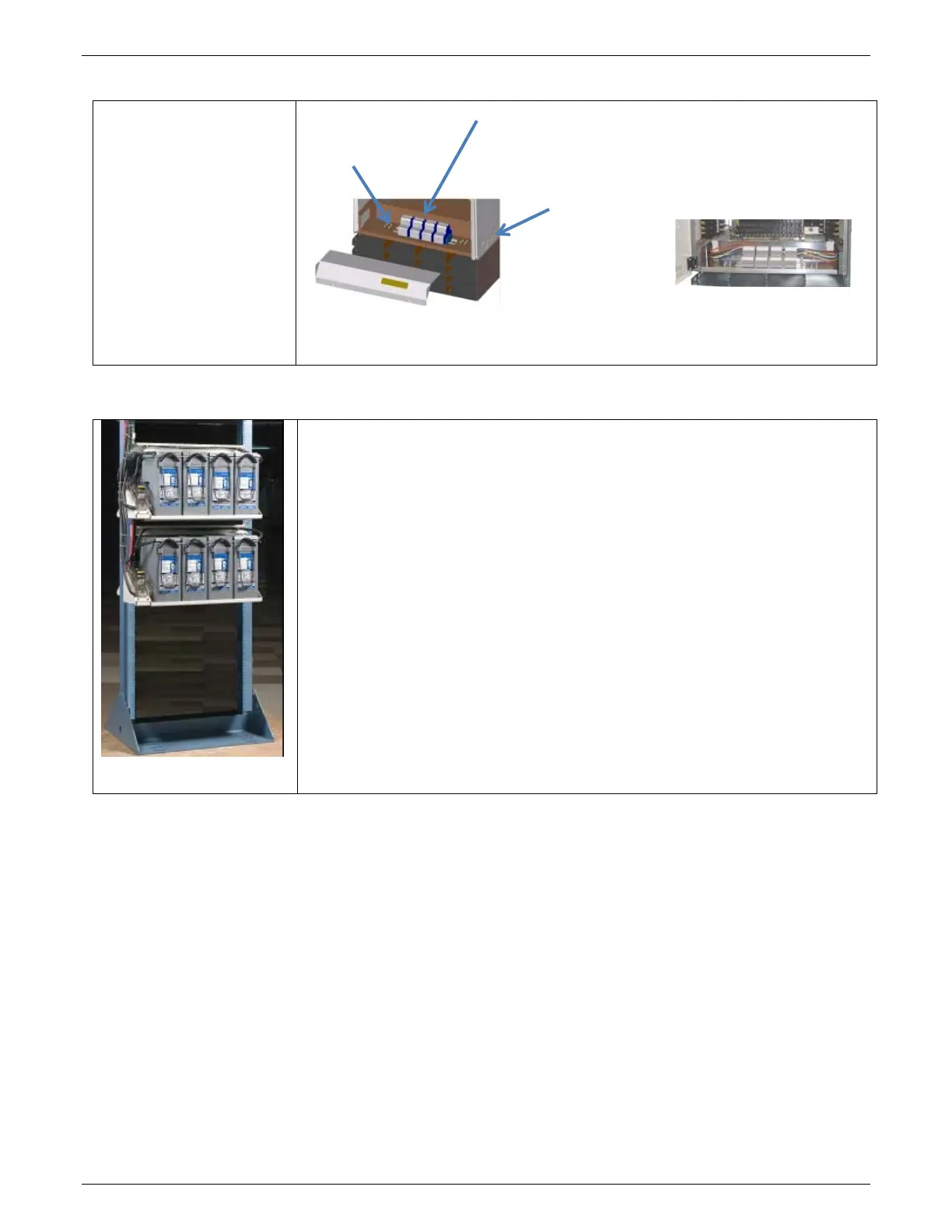
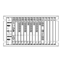
Power Input Panel
Power Input
Terminal blocks in a front
access panel at the bottom
of the distribution box.
Figure 7 Power Input Panel
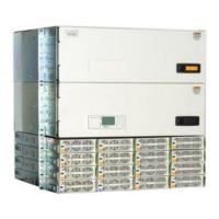
Battery Options and Monitoring Features
Figure 8 Battery Stand
Battery Options
• Designed for operation with GE flooded, VRLA and Durathon™ Sodium batteries, as
well as other vendors’ batteries.
• Battery trays are available for 100Ahr to 170Ahr batteries with Anderson
PowerPole® connectors or circuit breaker disconnects.
• Half-height and third-height systems can be mounted on floor-mounted VRLA
strings or on GE Universal Battery Stands.
Battery Monitoring Features
• Open String (OS) Alarms
• Emergency Power Off (EPO) for disconnecting batteries from the system
• Temperature/voltage probes (up to 16) used in Battery Management options
• Slope Thermal Compensation – High and Low Temperature
• Battery High Temp Disconnect
• Mid-String Voltage Monitoring
• Battery Discharge Test
• Battery Shunt
• Low Voltage Battery Disconnect/Reconnect Contactor (LVDB)
with Emergency Power Off (EPO)
each side:
(2) 1” and
Terminal Blocks Accept 24-
6 AWG wire.
Straps provided to
¼-20 x 0.75” or